DSC PG9916-PG89216-PG4916 - Smoke Detector W Heat - Installation Manual - Eng - S-Chi - R001

File Preview
Click below to download for free
Click below to download for free
File Data
| Name | dsc-pg9916-pg89216-pg4916-smoke-detector-w-heat-installation-manual-eng-s-chi-r001-9143276850.pdf |
|---|---|
| Type | |
| Size | 1.79 MB |
| Downloads |
Text Preview
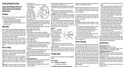
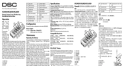
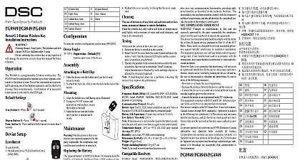
PG9916 PG8916 PG4916 Wireless PowerG Heat and Smoke Installation Instructions heat and smoke detectors provide open area protection and warning of developing fires by Activating a fire alarm upon either smoke or heat 60 Sounding an alarm with its built in alarm horn Transmitting an alarm signal to a compatible wireless alarm panel Test Mute switch functions during normal operation as a Test and during an alarm condition as a Mute switch Pressing Test Mute switch during an alarm condition stops the buzzer for 8 minutes If the condition is not restored after 8 minutes buzzer will resound Pressing the mute switch will not restore alarm condition tamper switch actuator is depressed when the unit is attached the mounting bracket Removal of the unit from the mounting causes the switch contacts to open transmitting a tamper to the alarm system control panel The detector is disabled not attached to the mounting bracket Setup The detector battery cover is fitted with a red button prevents the detector from locking onto the mounting bracket there is no battery inside The smoke detector is supplied with a CR123A battery To be installed by service persons in non hazardous loca only Batteries are to be replaced by service persons only Never remove batteries to stop a false alarm Open a or fan the air around the detector to clear the smoke The will turn itself off when the smoke is gone If false alarms attempt to clean the detector as described in this manual Do not stand close to the detector when the alarm is The alarm is loud in order to wake you in an emergency much exposure to the horn at close range may be harmful to hearing To keep the smoke detector in good working order you must it weekly To ensure the continued operation of all wireless devices performing a system default a global upload of all wireless via DLS is recommended before defaulting the sys After completing the system default download the wireless Buzzer Holes Test button and LEDs Bracket Detector 3 volt CR123A lithium consumer grade Battery terminals insulator Battery cover Enroll button Tamper switch When the battery first contact the alarm horn sound for 1 beep Hold the bracket with one Rotate the detector anticlock and pull it from the Connection and Initial Test Open detector Open battery cover Connect battery to ter verify correct Close the battery cover place the detector the mounting Press the Test button about 2 seconds When manually programming wireless devices if a device been powered up for more than 48 hours it cannot be enrolled the system until the device has been tampered and restored programming the panel using the Quick Enroll procedure the steps detailed in Enroll the Device into the System After restoring a low battery trouble the system may take up 5 minutes to clear the trouble the Device into the System quick enroll On a keypad press 8 Installer Code 804 000 Press and hold the device enroll button until the LED lights and then release the enroll button while the LED is still A confirmation message then appears on the keypad Press key to confirm ID Enter 3 digit zone Enter 3 digit zone type Enter 1 digit partition for all desired partitions and press using a menu based configuration scroll to the desired parti and press to toggle the partition On an LCD keypad enter the label by using word library pre enroll Remotely configure the unique ID number into the system For information see the HSM2HOST manual When on site press the device enroll button If the wireless device has been powered for more then 48 without being enrolled tamper and restore the device to it a Placement Test permanently mounting any wireless device temporarily the device and perform a placement test Tamper the device by removing the cover Restore the tamper The device now enters placement test mode 15 minutes The red LED blinks once to identify that a signal is being sent to receiver and then blinks three times to identify the signal The following table indicates the received signal Strength communication Response LED blinks LED blinks LED blinks blinks Only GOOD or STRONG signal strengths are If you receive a POOR signal from the device re locate and re test until a GOOD or STRONG signal is received For UL ULC installations only STRONG signal levels are After installation verify the product functionality in with the compatible receivers HSM2HOST9 HS2LC HS2ICNRF P 9 and PG9920 For detailed Placement instructions refer to the control panel Guide to Install Smoke Detectors detectors should always be installed in USA in accordance Chapter 29 of NFPA 72 the National Fire Alarm Code Where required by other governing laws codes or stan for a specific type of occupancy approved single and multi smoke alarms shall be installed as follows In all sleeping rooms and guest rooms Outside of each separate dwelling unit sleeping area within 21 ft m of any door to a sleeping room with the distance mea along a path of travel On every level of a dwelling unit including basements On every level of a residential board and care occupancy small including basements and excluding crawl spaces and attics In the living area s of a guest suite In the living area s of a residential board and care occupancy facility When mounting on ceiling the closest edge of the detector must at least 4 1m from the wall When mounting on wall the closest edge of the detector must be least 4 1m and no more than 12 3m from the ceiling When mounting on sloped gabled or peaked ceilings the hori distance of the furthest edge of the detector from the peak be no more than 3 ft 9m As required by the California State Fire Marshall warning fire detection is best achieved by the installation of detection equipment in all rooms and areas of the household as A smoke detector installed in each separate sleeping area in the but outside the bedrooms and 2 Heat or smoke detec in the living rooms dining rooms bedrooms kitchens hall attics furnace rooms closets utility and storage rooms and attached garages permanently mounting wireless device it is recom to mount the device and perform a test Mark and drill 2 holes in the surface Fasten the to the mounting sur with 2 screws Align bracket tabs with the detector slots and rotate the detector shown Pull the detector outward to verify that it is securely A battery must be inserted into the detector before the can be mounted onto the bracket Unauthorized removal of unit from the bracket will initiate a tamper alert enter the wireless configuration section enter 804 Zone Toggles Supervision Default Y supervision of the device and Visual Indications dual color LED buzzer and siren are used to signal various and trouble messages as shown below Indication LEDs alarm Flash every battery every sec every sec every sec every sec 30 sec sen trouble sensitiv alarm to clean 2 flashes Flashes 60 sec siren Detector Test every sec Indica or long beeps 4 sec beep 2 sec beep 30 sec beep 60 sec beep 30 sec short beeps 30 sec short tones 1.5 sec tamper alarm will mute for 3 minutes at first power on and revert to normal mode when the tamper switch condition is of 15 sec between buzzer beep and LED operation Replacement This product uses lithium batteries improper han may result in a HEAT EXPLOSION or FIRE causing per injury DO NOT recharge batteries Follow the battery safety instructions Dispose of used batteries in with the regulations in your area the detector battery lithium once every 8 years even if is no in