DSC PG9922 PG8922 PG4922 Instalation Manual EN FR SP PO R001
File Preview
Click below to download for free
Click below to download for free
File Data
| Name | dsc-pg9922-pg8922-pg4922-instalation-manual-en-fr-sp-po-r001-6319824705.pdf |
|---|---|
| Type | |
| Size | 1.21 MB |
| Downloads |
Text Preview
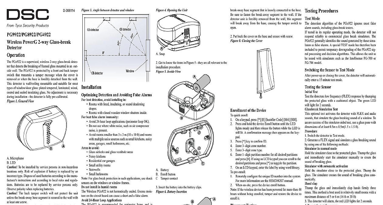
D 306114 3 Angle between detector and window 4 Opening the Unit PowerG 2 way Glass break PGx922 is a supervised wireless 2 way glass break detec that detects the breaking of framed glass mounted in an out wall The PGx922 is protected by a front and back tamper that transmits a tamper message when the cover is or when the base is forcibly detached from the wall detector is wall ceiling mountable and suitable for most of window door glass plated tempered laminated wired and sealed insulating glass No adjustment is necessary installation the detector is fully pre calibrated 1 General View Microphone LED To be installed by service persons in non hazardous only Risk of explosion if battery is replaced by an type Dispose of used batteries according to the manu instructions and according to local rules and regula Batteries are to be replaced by service persons only polarity when replacing batteries The back tamper switch will not protect the unit the break away base segment is secured to the wall with least one screw To ensure the continued operation of all wireless devices performing a system default a global upload of all wire programming via DLS is recommended before defaulting system After completing the system default download the programming Sensor acoustic sensor module of the PGx922 is omni directional full coverage Coverage is measured from the sensor the point on the glass farthest from the sensor The sensor can mounted as close as 1.5m 5 ft from the glass Figure 2 Typical Range Measurement mounted on opposite wall on adjoining walls or on the the range is 7.6 m 25 ft for plate tempered laminated coated and sealed insulating glass The coverage range depends on the angle between the detector and the glass a higher angle maximum range is reduced See the follow table for details degrees Range m ft 25 23 18 13 8 Detection and Avoiding False Alarms best detection avoid installing in Rooms with lined insulating or sound deadening Rooms with closed wooden window shutters inside best false alarm immunity Avoid 24 hour loop applications perimeter loop OK Do not use where white noise such as air compressor is present Avoid rooms smaller than 3 x 3 m 10 x 10 ft and rooms multiple noise sources such as small kitchens noisy garages small bathrooms etc to avoid Glass airlocks and glass vestibule areas Noisy kitchens Residential car garages Small utility rooms Stairwells Small bathrooms For glass break protection in such applications use shock on the windows or window frames not install in humid rooms Wireless PGx922 is not hermetically sealed Excess mois on the circuit board can cause a short and a false alarm 24 Hour Loop Applications PGx922 is recommended for perimeter loops and is to function in an occupied area In 24 hour loop appli where the sensor is armed all day and all night the alarm prevention technology will be pushed to its limit sounds can duplicate the glass break pattern the acoustic detects Install the PGx922 on a perimeter loop which is whenever the door and window contacts are armed Occupied Areas false alarm immunity is best in rooms with only moderate For 24 hour occupied area protection use shock sensors Testing PGx922 is designed to detect the breaking of framed glass in an outside wall Testing the sensor with unframed broken bottles etc may not trip the sensor The sensor does not trip to glass breaking in the middle of the The PGx922 may not consistently detect cracks in glass bullets which break through the glass Glass break sensors always be backed up by interior protection Travel Considerations the sound of breaking glass travels directionally out from broken window the best location for mounting the sensor is the opposite wall assuming the glass to be protected is the sensors range and line of sight The ceiling and side walls are also good sensor locations When on the opposite wall the detector should be mounted least 1.8m 6ft off the floor but not less than 30cm 12 the ceiling A ceiling mounted sensor will provide better if positioned 2 4 m 6 12ft away from the protected in the room is reduced with same wall mounting since such is partially dependent on glass break sound reflecting the opposite wall Installation Press in the snap and separate the cover from the base Snap Get to know the items in Figure 5 they are all relevant to the procedure 5 Inside View Battery Enroll button Tamper contact Insert the battery into the battery clips 6 Battery Insertion Negative terminal Positive terminal Polarity Risk of explosion if battery is replaced by an incor type Dispose of used battery according to manufacturers the Device Fasten the breakaway segment to the wall 7 PG9922 Internal View Mounting holes Break away base segment Back cover screw The PGx922 has a back tamper switch on the back pressing against the PCB As long as the PCB is seated within the base the switch will press against a special base segment that is loosely connected to the base sure to fasten the break away segment to the wall If the unit is forcibly removed from the wall this segment break away from the base causing the tamper switch to Put back the cover on the base and secure with screw 8 Closing the Cover of the Device quick enroll On a keypad press 8 Installer Code 804 000 and hold the device Enroll button until the LED steady and then release the button while the LED is lit A confirmation message then appears on the key key to confirm ID Enter 3 digit zone number Enter 3 digit zone type Enter 1 digit partition number for all desired partitions press If using an LCD keypad you can scroll to the partitions and press to toggxle the partition On an LCD keypad enter the label by using word library pre enroll Remotely configure the unique ID number into the system more information see the HSM2HOST manual When on site press the device enroll button If the wireless device has been powered for more then 48 without being enrolled tamper and restore the device to it Testing permanently mounting any wireless device temporarily the device and perform a Placement test Tamper the device by removing the cover Replace the cover to return the tamper switch to its normal After 2 seconds the transmit indicator blinks 3 times The table indicates received signal strength indica Strength communication Response LED blinks LED blinks LED blinks blinks Only GOOD or STRONG signal strengths are If you receive a POOR signal from the device re it and re test until a GOOD or STRONG signal is After installation verify the product functionality in con with the compatible receivers HSM2HOST9 HS2LC HS2ICNRF P 9 and PG9920 For detailed placement instructions refer to the control Reference Manual enter the wireless configuration section enter 804 Zone Toggles Supervision Default Y supervision of the device Procedures Mode detection algorithm of the PGx922 ignores most false sounds including glass break testers tested in its regular operating mode the detector will not reliably to commercial glass break simulators The generally identifies the sound generated by these simu as false alarms A special TEST mode has therefore been to permit temporary downgrading of the PGx922 sig processing and decision algorithms This allows the unit to tested with simulators such as the Intellisense FG 700 or model the Sensor to Test Mode power up or closing the cover the detector will automati enter a 15 minute test mode the Sensor Test the detectors low frequency FLEX response by thumping protected glass with a cushioned object The green LED light for 2 seconds Simulation Test optional test activates the detector with FLEX and audio that simulate the glass breaking sound of a window To success of the simulator aided test use a glass pane w