DSC PG9924-8924-4924 V1 - Installation Manual - EN FR ES PT
File Preview
Click below to download for free
Click below to download for free
File Data
| Name | dsc-pg9924-8924-4924-v1-installation-manual-en-fr-es-pt-9021748653.pdf |
|---|---|
| Type | |
| Size | 2.62 MB |
| Downloads |
Text Preview
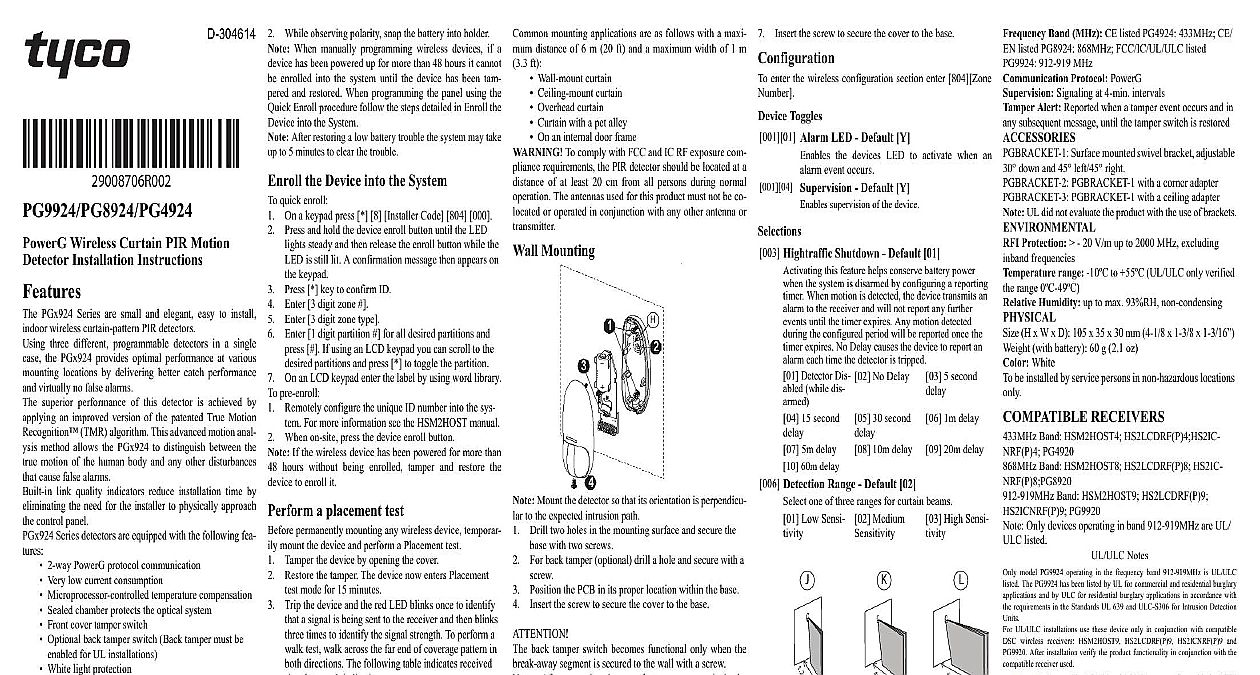
D 304614 Wireless Curtain PIR Motion Installation Instructions PGx924 Series are small and elegant easy to install wireless curtain pattern PIR detectors three different programmable detectors in a single the PGx924 provides optimal performance at various locations by delivering better catch performance virtually no false alarms superior performance of this detector is achieved by an improved version of the patented True Motion TMR algorithm This advanced motion anal method allows the PGx924 to distinguish between the motion of the human body and any other disturbances cause false alarms link quality indicators reduce installation time by the need for the installer to physically approach control panel Series detectors are equipped with the following fea 2 way PowerG protocol communication Very low current consumption Microprocessor controlled temperature compensation Sealed chamber protects the optical system Front cover tamper switch Optional back tamper switch Back tamper must be for UL installations White light protection Elegantly styled sturdy case RF Link quality indication Setup To be installed by service persons in non hazardous only Risk of explosion if battery is replaced by an type Observe polarity when installing batteries of used batteries according to the manufacturer and according to local rules and regulations Bat are to be replaced by service persons only To ensure the continued operation of all wireless after performing a system default a global upload of wireless programming via DLS is recommended before the system After completing the system default the wireless programming Enroll button Front tamper switch RF Module Sensor LEDs Back tamper switch shown Switch is back side of PCB 3 Volt Lithium battery Breakaway Locking plate Low Sensitivity Medium Sensitivity High Sensitivity Top Side the battery Unscrew the cover While observing polarity snap the battery into holder When manually programming wireless devices if a has been powered up for more than 48 hours it cannot enrolled into the system until the device has been tam and restored When programming the panel using the Enroll procedure follow the steps detailed in Enroll the into the System After restoring a low battery trouble the system may take to 5 minutes to clear the trouble the Device into the System quick enroll On a keypad press 8 Installer Code 804 000 Press and hold the device enroll button until the LED steady and then release the enroll button while the is still lit A confirmation message then appears on keypad Press key to confirm ID Enter 3 digit zone Enter 3 digit zone type Enter 1 digit partition for all desired partitions and If using an LCD keypad you can scroll to the partitions and press to toggle the partition On an LCD keypad enter the label by using word library pre enroll Remotely configure the unique ID number into the sys For more information see the HSM2HOST manual When on site press the device enroll button If the wireless device has been powered for more than hours without being enrolled tamper and restore the to enroll it a placement test permanently mounting any wireless device temporar mount the device and perform a Placement test Tamper the device by opening the cover Restore the tamper The device now enters Placement mode for 15 minutes Trip the device and the red LED blinks once to identify a signal is being sent to the receiver and then blinks times to identify the signal strength To perform a test walk across the far end of coverage pattern in directions The following table indicates received strength indication Strength response LED blinks LED blinks GOOD LED blinks blinks communication Only GOOD or STRONG signal strengths acceptable If you receive a POOR signal from the device it and re test until a GOOD or STRONG signal is For UL ULC installations only STRONG signal levels acceptable After installation verify the product function HS2LCDRF P 9 HS2ICNRF P 9 For detailed placement instructions refer to the control reference manual the Device PowerG Series wireless PIR Motion detectors shall be and used within an environment that provides the degree max 2 and overvoltages category II The is designed to be installed only by qualified ser persons conjunction with compatible Keep away from heat sources Do not expose to air drafts Do not install outdoors Avoid direct sunshine Keep wiring away from power cables Do not install behind partitions Mount on solid stable surface Installed in accordance with NEC NFPA 70 Installed in accordance with UL 681 Standard for and Classifications of Burgler and Holdup Systems mounting applications are as follows with a maxi distance of 6 m 20 ft and a maximum width of 1 m ft Wall mount curtain Ceiling mount curtain Overhead curtain Curtain with a pet alley On an internal door frame To comply with FCC and IC RF exposure com requirements the PIR detector should be located at a of at least 20 cm from all persons during normal The antennas used for this product must not be co or operated in conjunction with any other antenna or Mounting Mount the detector so that its orientation is perpendicu to the expected intrusion path Drill two holes in the mounting surface and secure the with two screws For back tamper optional drill a hole and secure with a Position the PCB in its proper location within the base the screw to secure the cover to the base back tamper switch becomes functional only when the segment is secured to the wall with a screw After mounting be sure that no gaps remain in the housing For example in the area around the screw Do not remove the battery with a screwdriver Mounting the screw to secure the cover to the base enter the wireless configuration section enter 804 Zone Toggles Alarm LED Default Y the devices LED to activate when an event occurs Supervision Default Y supervision of the device Hightraffic Shutdown Default 01 this feature helps conserve battery power the system is disarmed by configuring a reporting When motion is detected the device transmits an to the receiver and will not report any further until the timer expires Any motion detected the configured period will be reported once the expires No Delay causes the device to report an each time the detector is tripped Detector Dis while dis 15 second 5m delay 60m delay 30 second 10m delay 5 second 20m delay No Delay 1m delay Detection Range Default 02 one of three ranges for curtain beams Low Sensi Medium High Sensi 12ft 18ft Mount the detector so that its orientation is perpendic to the expected intrusion path When mounting using the the back tamper becomes inoperative The PGx924 can mounted on either side of a window The bracket provides mounting options For optimum angle coverage use these two holes to shift the coverage angle away from wall by 5 use these two holes to shift the coverage angle away from wall by 10 Using the bracket as a guide drill two 7 mm 1 4 holes the marked locations Secure the bracket with two supplied screws Place the base slots over the two bracket pins Place the locking plate over the two pins Secure the locking plate by pressing downward Position the PCB correctly in the base Type Dual element low noise pyroelectric sensor of Curtain Beams 2 Settings Maximum 6 m Medium 4 m and Mini 1.2 2m remotely selected 3V Lithium battery type CR 123A or equivalent For UL installations use Gold Peak GP only Us