DSC PG9974(P)-8974(P)-4974(P) Installation Manual ENG FRE SPA POR - 29008702R001

File Preview
Click below to download for free
Click below to download for free
File Data
| Name | dsc-pg9974-p-8974-p-4974-p-installation-manual-eng-fre-spa-por-29008702r001-2967531408.pdf |
|---|---|
| Type | |
| Size | 2.44 MB |
| Downloads |
Text Preview
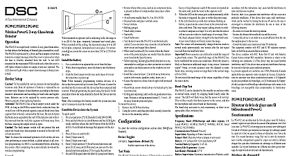
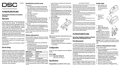
D 304674 the Battery PowerG High security Mirror Detector Anti masking Installation Instructions PGx974 P pet immune are 2 way microprocessor con wireless digital mirror PIR detectors which include the features Built in link quality indicators reduce installation time by the need for the installer to physically approach control panel Adaptive Active Infra Red Anti Masking technology the most advanced reliable protection against masking attempts patent pending Includes a fully supervised PowerG transceiver Incorporates patent pending black mirrors for extremely white light immunity Advanced elliptical parabolic mirror technology V slot optic technology patented for improved anti vandalism and for very high reliability Creep zone protection PGx974P can distinguish between human beings and pets up to 18 kg 40 lb The advanced True Motion Recognition algorithm distinguishes between the true motion of an and any other disturbances which may cause false No vertical adjustment is needed Motion event counter determines whether 1 or 2 motion events will trigger an alarm Automatic termination of walk test after 15 minutes Microprocessor controlled temperature compensation Sealed chamber protects the optical system Front and back tamper protection Self test Setup To ensure the continued operation of all wireless devices performing a system default a global upload of all wire programming via DLS is recommended before defaulting system After completing the system default download the programming Screw cover LED PIR optical window Enroll button use a screwdriver to press the recessed but Battery Tamper switch Break away base segment shaded Mounting height Coverage range Horizontal view Vertical view Lower surface with downward tilt Upper surface without downward tilt Risk of explosion if battery is replaced by an incor type Dispose of used batteries according to the manufac instructions and according to local rules and regulations are to be replaced by service persons only On the indicated location lift the screw cover upward using thumb the arrow Release the screw and open the cover in the direction shown Insert a screwdriver into the slot and then push inward to sep the base from the cover Insert battery while observing polarity When manually programming wireless devices if a has been powered up for more than 48 hours it cannot be into the system until the device has been tampered and When programming the panel using the Quick Enroll follow the steps detailed in Enroll the Device into the After restoring a low battery trouble the system may take to 5 minutes to clear the trouble the Device into the System quick enroll On a keypad press 8 Installer Code 804 000 Press and hold the device enroll button until the LED lights and then release the enroll button while the LED is lit A confirmation message then appears on the keypad Press key to confirm ID Enter 3 digit zone Enter 3 digit zone type Enter 1 digit partition for all desired partitions and press If using an LCD keypad you can scroll to the desired par and press to toggle the partition On an LCD keypad enter the label by using word library pre enroll Remotely configure the unique ID number into the system more information see the HSM2HOST manual When on site press the device enroll button If the wireless device has been powered for more than 48 without being enrolled tamper and restore the device to it a Placement Test permanently mounting any wireless device temporarily the device and perform a Placement test Tamper the device by removing the cover Restore the tamper The device now enters Placement test for 15 minutes Trip the device and the red LED blinks once to identify that a is being sent to the receiver and then blinks three times identify the signal strength To perform a walk test walk the far end of coverage pattern in both directions The table indicates the received signal strength indica Response LED blinks LED blinks LED blinks blinks Only GOOD or STRONG signal strengths are If you receive a POOR signal from the device re Strength communication it and re test until a GOOD or STRONG signal is For UL ULC installations only STRONG signal levels acceptable After installation verify the product functional in conjunction with the compatible receivers HSM2HOST9 HS2ICNRF P 9 and PG9920 For detailed Placement instructions refer to the control Reference Guide Perform a walk test of the coverage area at least once a to ensure that the detector is working correctly Mount the detector so that its orientation is perpendicular the expected intrusion path For the desired detector range height use mounting holes x or y as specified in the table To be installed by service persons in non hazardous loca only the following as a guide for locating a suitable mounting Keep away from heat sources Do not expose to air drafts Do not install outdoors Avoid direct sunshine Keep wiring away from power cables Do not install behind partitions Mount on solid stable surface m 3.0 2.7 2.4 2.1 1.8 ft m The back tamper switch will not protect the unit the break away base segment is secured to the wall with least one screw enter the wireless configuration section enter 804 000 Toggles Alarm LED Default Y the devices LED to activate when an alarm occurs Supervision Default Y supervision of the device Hightraffic Shutdown Default 01 this feature helps conserve battery power the system is disarmed by configuring a reporting When motion is detected the device transmits an to the receiver and will not report any further until the timer expires Any motion detected the configured period will be reported once the expires No Delay causes the device to report an each time the detector is tripped Detector Dis while dis 15 second 5m delay 60m delay 30 second 10m delay 5 second 20m delay No Delay 1m delay Event counter Default 002 activates after a configured number of events been detected in activities Indications Indications LED blinks LED ON 0.2 sec on 2 sec LED on LED blinks slowly sec ON 30 sec OFF warm up 120 open close alarm detection Diagnostic detection Normal failure Normal failure Diagnostic Indications and red LED blink 0.2 sec ON 0.2 sec OFF and red LED blink slowly 0.2 ON both 30 sec OFF Type Dual element low noise pyroelectric sensor Data of Beam Elements 18x3 54 far parabolic mirror seg m ft m ft m ft Coverage 15 m 49 ft 90 m 82 ft x 2.5 m Immunity only Up to 38 kg 85 lb Battery 3V Lithium battery type CR 123A option can be used type CR 17450 For UL installations use Gold Peak GP only Use only above battery type Battery Capacity 1450 mA h 2400mA h for CR17450 Battery Threshold 2.45 V Life for typical use 7 years not tested by UL ULC Motion Event Verification 2 remote selections 1 or 2 ON motion events Period 2 seconds Band MHz CE Listed PG4974 433MHz CE listed PG8974 868MHz FCC IC UL ULC listed PG9974 Protocol PowerG Signaling at 4 min intervals Alert Reported when a tamper event occurs and in subsequent message until the tamper switch is restored 1.8 3.0 m 6 10 ft Options Surface or corner