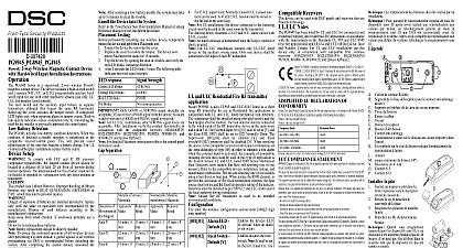
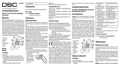
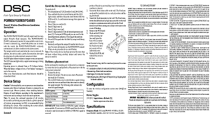
DSC PG9975-PG8975-PG4975 - Door and Window Contact - Installation Guide - EN-FR-ES-PO - R002

File Preview
Click below to download for free
Click below to download for free
File Data
| Name | dsc-pg9975-pg8975-pg4975-door-and-window-contact-installation-guide-en-fr-es-po-r002-8213547069.pdf |
|---|---|
| Type | |
| Size | 1.81 MB |
| Downloads |
Text Preview
D 304589 the battery at an angle observing battery and then press down the battery DSC wireless Series Wireless Door and Contact Installation PG9975 PG8975 PG4975 Door and Window Contacts are supervised PowerG magnetic contact devices They a built in reed switch that opens upon removal of a placed near it The device transmits alarm notifications the control panel and is supervised using the PowerG 2 way protocol The LED lights green yellow red to signal strength upon first insertion of the battery for the test period of 15 min LED does not light while a or alarm message is being transmitted Operating is obtained from an on board 3 V Lithium battery Built link quality indicators reduce installation time by eliminating need for the installer to physically approach the control For UL ULC installations use this device only in con with HS2LCDRF P 9 HS2ICNRF P 9 and PG9920 Detection PGx975 includes low battery condition detection When condition is detected a trouble message is transmitted to the receiver control panel This will provide visual of the unit that requires a battery change Setup product uses Lithium Batteries Improper handling of lith batteries may result in HEAT GENERATION EXPLO or FIRE which may lead to personal injuries OF EXPLOSION BATTERIES ARE INCORRECTLY REPLACE ONLY WITH THE OR EQUIVALENT TYPE RECOMMENDED BY MANUFACTURER DISPOSE OF USED BATTERIES TO THE MANUFACTURER INSTRUC AWAY FROM SMALL CHILDREN IF SWAL PROMPTLY SEE A DOCTOR not try to recharge these batteries Installation and battery replacement should be done by persons in indoor non hazardous locations only To ensure the continued operation of all wireless devices performing a system default a global upload of all wire programming via DLS is recommended before defaulting system After completing the system default download the programming Enroll button Battery Polarity Reed switch on underside of PC Board in unit Symbol on side of the case indicates location of reed space maximum 6mm Magnet Back Tamper break away base segment PG8975 only Mounting holes the battery a 4 mm flat screwdriver into the slot of the plastic and flex the slot to open that side of the plastic the screwdriver into the slot on the other side of the cover and repeat the procedure and then remove cover When manually program wireless devices if a device been powered up for more 48 hours cannot be into the system until the has been tampered and When programming the using the Quick Enroll procedure follow the steps in Enroll the Device into the System After restoring a low battery trouble the system may take to 5 minutes to clear the trouble the Device into the System quick enroll On a keypad press 8 Installer Code 804 000 and hold the device enroll button until the LED lights and then release the enroll button while the LED is lit A confirmation message then appears on the key key to confirm ID Enter 3 digit zone Enter 3 digit zone type Enter 1 digit partition for all desired partitions and If using an LCD keypad you can scroll to the partitions and press to toggle the partition On an LCD keypad enter the label by using word library pre enroll Remotely configure the unique ID number into the system more information see the HSM2HOST manual When on site press the device enroll button If the wireless device has been powered for more then 48 without being enrolled tamper and restore the device to it the Device is highly recommended to attach the transmitter to the top of door window on the fixed frame and the magnet to the door window Ensure that the magnet is located not more than 6 0.25 in from the transmitter marked side Testing permanently mounting any wireless device temporarily the device and perform a placement test Tamper the device by removing the cover Replace the cover to restore the tamper Trip the device by opening the door or window and verify red LED blinks indicating detection After 2 seconds the LED blinks 3 times The following indicates received signal strength Strength communication response LED blinks LED blinks LED blinks blinks Only GOOD or STRONG signal strengths are If you receive a POOR signal from the device re it and re test until a GOOD or STRONG signal is For UL ULC installations only STRONG signal levels acceptable After installation verify the product functional in conjunction with the compatible receivers HSM2HOST9 HS2ICNRF P 9 and PG9920 For detailed placement instructions refer to the control Reference Guide Separation Ferrous Materials 12mm 20mm 27mm of the Mag X Y Z maximum gap separation for installation on materials and axes of use is 6mm 0.24 For EN50131 2 6 compliant installations use contact and only for axis X movement when installed on metallic materials Procedure Adhesive tape not to be used for EU Market PG4975 and PG9975 away the release liners from the two strips of double adhesive tape and attach to the device and magnet Align the device with the magnet according to the location and fasten the device and magnet to the mounting PG8975 Mark and drill 2 holes in the mounting surface 3 holes for tamper Fasten the base with the screws the screws sure that screw heads pressed the sur of the plastic and per to the cover Align the device the magnet to the marks and fasten the device and magnet to the surface enter the wireless configuration section enter 804 Zone Toggles Supervision Default Y supervision of the device Band MHz CE Listed PG4975 433MHz CE listed PG8975 868MHz FCC IC UL ULC listed PG9975 GFSK Protocol PowerG Signaling at 256 sec intervals 3 V Lithium CR2032 type battery Varta 230mAh Life Expectancy 5 years not tested by UL ULC Current 4 Battery Threshold 2.1 V Temperature 10 to 55 UL only verified range 0 up to max 93 RH UL only verified up to max LxWxD 62 x 25.4 x 6.1 mm 2 1 2 x 1 x 1 4 in including battery 12g 0.42 oz White or brown Receivers Band HSM2HOST4 HS2LCDRF P 4 HS2IC PG4920 Band HSM2HOST8 HS2LCDRF P 8 HS2IC PG8920 Band HSM2HOST9 HS2LCDRF P 9 HS2IC PG9920 Only devices operating in band 912 919MHz are UL listed Only model PG9975 operating in the frequency band is UL ULC listed Notes PG9975 has been listed by UL ULC for residential bur applications in accordance with the requirements in the UL 634 and ULC ORDC634 for Door and Window UL ULC installations use this device only in conjunction compatible DSC wireless receivers HSM2HOST9 HS2ICNRF P 9 and PG9920 The PG4975 and PG8975 are compliant the RTTE requirements Directive 1999 5 EC the European Parliament and of the Council of 9 1999 The PG8975 is certified by Applica and Certification to the following standards EN50131 2 6 GRADE 2 CLASS II EN50131 6 Type C Test and Certification has certified only the 868 MHz of this product According to EN 50131 1 2006 and this equipment can be applied in installed systems up and including Security Grade 2 Environmental Class II UK PG8975 is suitable for use in systems installed to conform PD6662 2010 at Grade 2 and environmental class 2 BS8243 Power G peripheral devices have two way communication providing additional benefits as described in the brochure This functionality has not been tested to with the respective technical requirements and should be considered outside the scope of the product


