DSC PG9985-PG8985-PG4985 Installation Manual ENG FRE SPA POR - 29008704R001

File Preview
Click below to download for free
Click below to download for free
File Data
| Name | dsc-pg9985-pg8985-pg4985-installation-manual-eng-fre-spa-por-29008704r001-4769280153.pdf |
|---|---|
| Type | |
| Size | 2.39 MB |
| Downloads |
Text Preview
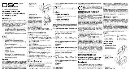
D 304678 Wireless Flood Detector Installation PG9985 PG8985 PG4985 are fully supervised two way PowerG flood detectors The PG9985 PG8985 continuously monitor for unacceptable water levels water is detected e g when both probes are in contact the water the PG9985 PG8985 PG4985 wirelessly an alarm condition to the alarm system tamper switch is activated when the cover is removed In the device sends a probe disconnection alert upon detection of a probe terminal connection failure LED lights whenever alarm or tamper events are reported LED does not light while a supervision message is being power is obtained from a 3V Lithium battery the battery voltage is low a battery message is to the receiver every flood detection each flood detector should be and dried Setup To be installed by service persons in non hazardous only Risk of explosion if battery is replaced by an type Observe polarity when installing batteries of used batteries according to the manufacturer and according to local rules and regulations To ensure the continued operation of all wireless after performing a system default a global upload of wireless programming via DLS is recommended before the system After completing the system default the wireless programming Transmission LED Terminal block for sensor Enroll button Tamper switch Mounting holes Break away tamper the battery a flat edged screw into the slot and upward to remove Remove the screw separate the from the base Observe polarity install battery Connect the sensor wire to the block When manually programming devices if a device has powered up for more than 48 it cannot be enrolled into the until the device has been and restored When programming the panel using Quick Enroll procedure follow the steps detailed in Enroll Device into the System After restoring a low battery trouble the system may up to 5 minutes to clear the trouble the Device into the System quick enroll On a keypad press 8 Installer Code 804 000 Press and hold the device enroll button until the LED steady and then release the enroll button while the is still lit A confirmation message then appears on keypad Press key to confirm ID Enter 3 digit zone Enter 3 digit zone type Enter 1 digit partition for all desired partitions and If using an LCD keypad you can scroll to the partitions and press to toggle the partition On an LCD keypad enter the label by using word library pre enroll Remotely configure the unique ID number into the sys For more information see the HSM2HOST manual When on site press the device enroll button If the wireless device has been powered for more than hours without being enrolled tamper and restore the to enroll it a placement test permanently mounting any wireless device temporar mount the device and perform a Placement test with the sensor connected Tamper the device Restore the tamper The device now enters Placement mode for 15 minutes The red LED blinks once to identify that a signal is being to the receiver and then blinks three times to identify signal strength The following table indicates the signal strength conjunction with Strength communication response LED blinks LED blinks LED blinks blinks Only GOOD or STRONG signal strengths acceptable If you receive a POOR signal from the device it and re test until a GOOD or STRONG signal is For UL ULC installations only STRONG signal levels acceptable After installation verify the product function HS2LCDRF P 9 HS2ICNRF P 9 For detailed Placement instructions refer to the control Reference Guide the Device Avoid mounting the transmitter portion of the device a metal object such as a washing machine refrigera or freezer RF signals can be affected by metal objects every flood detection each flood detector should be and dried Otherwise the unit may not operate as due to the nature of different liquids Adhesive tape not to be used for EU Market compatible locating metal the flood sensor in the lowest point in the room or water is expected to pool with at least 2 supplied The flood sensor must be mounted so both of the device are touching water when an alarm is desired Secure the flood sensor cable to the wall The flood sen should be installed only in a vertical position and fac downward Attach the flood transmitter to the wall The flood trans should be placed as high up as possible on the wall improve communication and to prevent the flood itself from coming into contact with water in the of flooding Remove the PCB board Mark and drill 2 holes the mounting sur and fasten the with 2 counter screws If using break away tam secure with an screw Reattach the PCB and the cover to base External wiring shall be routed and protected in a man that prevents excessive strain on wire and terminal connections loosening of terminal connections damage of conductor insulation developing any other type of hazard e g tripping due loose cables enter the wireless configuration section enter 804 Zone Toggles Supervision Default Y supervision of the device Band CE Listed PG4985 433MHz CE EN PG8985 868MHz FCC IC UL ULC listed PG9985 MHz Protocol PowerG Input External flood probe Signaling at 4 min intervals type 3 V Lithium CR 123 type battery Panasonic GP only Life Expectancy 8 years not tested by UL ULC Battery Threshold 2.2 V Supervision Automatic transmission of battery data as part of periodic status report and immedi upon low battery condition detection Range 10 to 55 UL ULC only veri the range 0 to 49 up to max 93 RH non condensing LxWxD 81 x 34 x 25 mm 3 3 16 x 1 1 4 x 1 in including battery 53g 1.9 oz Receivers Band HSM2HOST4 HS2LCDRF P 4 HS2IC PG4920 Band HSM2HOST8 HS2LCDRF P 8 HS2IC Band HSM2HOST9 HS2LCDRF P 9 PG9920 Only devices operating in band 912 919MHz are UL listed Notes model PG9985 operating in the frequency band 912 919MHz are UL ULC listed The PG9985 has listed by UL cUL under UL2017 requirements UL ULC installations use these devices only in conjunction with compatible DSC wireless receivers HS2LCDRF P 9 HS2ICNRF P 9 and PG9920 After installation verify the product in conjunction with the compatible receiver used The PG8985 and PG4985 are compliant with the RTTE requirements 1999 5 EC of the European Parliament and of the Council of 9 March 1999 Power G peripheral devices have two way communication functionality additional benefits as described in the technical brochure This has not been tested to comply with the respective technical requirements and should be considered outside the scope of the product certification COMPLIANCE STATEMENT Changes or modifications to this unit not expressly approved by the party responsible for could void the user authority to operate the equipment device has been tested and found to comply with the limits for a Class B digital device pursuant to 15 of the FCC Rules These limits are designed to provide reasonable protection against harmful in residential installations This equipment generates uses and can radiate radio frequency and if not installed and used in accordance with the instructions may cause harmful interference radio and television reception there is no guarantee that interference will not occur in a particular installation If this device cause such interference which can be verified by turning the device off and on the user is to eliminate the interference by one or more of the following measures Re orient or re locate the receiving antenna Increase the distance between the device and the receiver Connect the device to an outlet on a circuit different from the one that