DSC PG9994 PG8994 PG4994 PowerG High-Security Outdoor PIR Motion Mirror Detector - Installation Instructions

File Preview
Click below to download for free
Click below to download for free
File Data
| Name | dsc-pg9994-pg8994-pg4994-powerg-high-security-outdoor-pir-motion-mirror-detector-installation-instructions-1097843652.pdf |
|---|---|
| Type | |
| Size | 2.32 MB |
| Downloads |
Text Preview
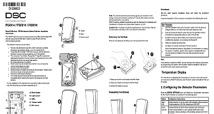
D 304675 High Security Outdoor PIR Motion Detector Installation Instructions PGx994 is a PowerG wireless outdoor digital mirror PIR which uses eight PIR sensors each acting as a Quad to accurately and reliably determine whether an alarm justified Features benefits include Optimum performance even in poor weather conditions as snow rain dust wind and direct sunlight Tamper protection prevents opening and removal from wall Built in link quality indicators reduce installation time by the need for the installer to physically approach control panel Microprocessor controlled compensation Immunity to pets weighing up to 18 Kg 40lb Pet immunity feature has not been evaluated to UL 639 ULC S306 03 due to the feature not being addressed in standard Setup To comply with FCC and RF exposure compliance require the PIR detector should be at a distance of at least 20 cm all persons during normal opera The antennas used for this product not be co located or operated in with any other antenna or The PG Series wireless PIR detectors shall be installed and within an environment that pro the pollution degree max 2 and overvoltages category II NON HAZARDOUS LOCATIONS The equipment is to be installed only by qualified service persons To ensure the continued operation of all wireless devices performing a system default a global upload of all wire programming via DLS is recommended before defaulting system After completing the system default download the programming LED Enroll button Tamper switch Bracket release Horizontal view of coverage area Vertical view of coverage area Vertical angle For wall tamper Back tamper switch is required for UL commercial bur installations the battery is recommended to perform the first battery installation on a surface After battery insertion the LED will flash for 60 and then the detector will enter a 15 minute local diag mode When manually programming wireless devices if a has been powered up for more than 48 hours it cannot be into the system until the device has been tampered and When programming the panel using the Quick Enroll follow the steps detailed in Enroll the Device into the After restoring a low battery trouble the system may take to 5 minutes to clear the trouble the Device to the PowerSeries Neo Host Installation Manual or Reference Manual for the enrollment procedure and Walk Testing permanently mounting any wireless device temporarily the device and perform a Placement test Perform a walk of the coverage area at least once a year to ensure that the is working correctly Tamper the device by removing the cover Restore the tamper device now enters test mode 15 minutes Trip the device and red LED blinks to identify that a is being sent to receiver and then three times to the signal To perform a test walk across far end of pattern in directions The table received strength indication response LED blinks LED blinks LED blinks blinks Strength communication Only GOOD or STRONG signal strengths are If you receive a POOR signal from the device re it and re test until a GOOD or STRONG signal is For UL ULC installations only STRONG signal levels acceptable After installation verify the product functional in conjunction with the compatible receivers For detailed placement instructions refer to the control Reference Guide the Device Notes The top cover should only be accessed by service personnel or manufacturer Do not obscure detector field of view with large objects Install in position that expected intruder motion is perpendicular to the zones detection triggered by conditions such as weather blowing leaves brush or related environmental conditions etc need to be when assessing the installation and application If trips are not tolerable it is recommended that the wire outdoor detector is enrolled to a zone that is defined as a alarm circuit Risk of explosion if incorrect battery is used Dispose used batteries according to the manufacturer instructions according to local rules and regulations Batteries are to be by service persons only Mirror Max Coverage At least 12 m 40 ft 90 Technology 8 independent quad PIR detectors oper in true Quad configuration Immunity Up to 18 Kg 40 lb Power Two 3V CR123A Lithium batteries For UL installations use Gold Peak GP or Panasonic batteries only Life for typical use minimum one year typical 3 not verified by UL ULC Battery Threshold 4.0 V Band MHz CE Listed PG4994 433MHz CE listed PG8994 868MHz FCC IC UL ULC listed PG9994 Protocol PowerG Alert Reported when a tamper event occurs and in any message until the tamper switch is restored type Wall mounting Height 1.5 3.0 m 5 10 ft Must be 8 feet for listed installations Adjustment 45 to 45 in 5 steps Adjustment 0 to 10 in 2.5 steps range 40 to 70 UL ULC only verified range 35 to 66 Humidity up to max 93 RH non condensing Light Immunity Above 25000 lux Rating 55 HxLxW 157 x 147 x 124 mm 6 3 16 x 5 13 16 x 4 7 8 with battery 600 g 21 oz White or gray RECEIVERS device can be used with DSC panels and receivers that use technology UL ULC installations use the device only with compatible wireless receivers WS900 19 WS900 29 HS2LCDRF P 9 HS2ICNRF P 9 and PG9920 installation verify the product functionality in conjunction the compatible receiver used Only models PG9994 PG9994P operating in the fre band 912 919MHz are UL ULC listed Notes PG9994 PG9994P has been listed by UL for commercial residential burglary applications and by ULC for residential applications in accordance with the requirements in Standards UL 639 and ULC S306 for Intrusion Detection PG8994 is certified by Applica Test and Certification to the standards EN50131 2 2 GRADE 2 CLASS IV Type C Applica Test and Certification has certified the 868 MHz variant of this product According to EN and A1 2009 this equipment can be applied in systems up to and including Security Grade 2 Envi Class II UK The PG8994 is suitable for use in sys installed to conform to PD6662 2010 at Grade 2 and class 2 BS8243 The Power G peripheral devices two way communication functionality providing addi benefits as described in the technical brochure This has not been tested to comply with the respective requirements and should therefore be considered out the scope of the product certification EU DECLARATION OF CONFORMITY Tyco Safety Products Canada Ltd declares that the radio equipment is in compliance with Directive 2014 53 EU The full text of the EU of conformity for the models mentioned below are available at the internet addresses http dsc com pdf 1401023 http dsc com pdf 1401046 Band Maximum Power 433.04MHz 434.79MHz 10mW 868.0MHz 868.6MHz 10mW 868.7MHz 869.2MHz 10mW single point of contact Tyco Safety Products Voltaweg 20 6101 Echt Netherlands COMPLIANCE STATEMENT Changes or modifications to this unit not expressly approved by the responsible for compliance could void the user authority to operate the device has been tested and found to comply with the limits for a Class B digital pursuant to Part 15 of the FCC Rules These limits are designed to provide protection against harmful interference in residential installations This generates uses and can radiate radio frequency energy and if not installed used in accordance with the instructions may cause harmful interference to radio television reception However there is no guarantee that interference will not in a particular installation If this device does cause such interference which be verified by turning the device off and on the user is encouraged to eliminate interference by one or more of the following measures