DSC PGx935 Shock Sensor - Installation Instructions - EN-FR-ES-PO

File Preview
Click below to download for free
Click below to download for free
File Data
| Name | dsc-pgx935-shock-sensor-installation-instructions-en-fr-es-po-8620713954.pdf |
|---|---|
| Type | |
| Size | 3.10 MB |
| Downloads |
Text Preview
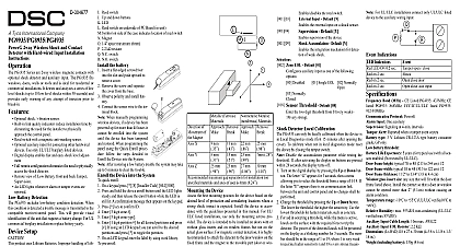
D 304677 2 way Wireless Shock and Contact with Hardwired Input Installation PGx935 series are 2 way shock detectors with an optional accumulation feature and auxiliary input The PGx935 windows doors walls or roofs and is ideal for residential or installations Optional shock accumulation vibration sensor Built in link quality indicators reduce installation time by the need for the installer to physically approach control panel Reed switch Optional auxiliary input for connecting other hardwired Use only UL ULC burglary listed devices Digital display enables fast and easy shock level adjustment Full remote configuration eliminates the need to physically the shock detector Remote view of Low Battery front and back Tamper An LED lights when alarm or tamper events are reported detection PGx935 includes low battery condition detection When condition is detected a trouble message is transmitted to the receiver control panel This will provide visual of the unit that requires a battery change For UL burglary installations replace battery yearly setup This product uses Lithium Batteries Improper of lithium batteries may result in HEAT GENERA EXPLOSION or FIRE which may lead to personal inju To be installed by service personnel only DANGER OF EXPLOSION IF BATTERIES ARE INCORRECTLY REPLACE ONLY WITH THE OR EQUIVALENT TYPE RECOMMENDED BY THE DISPOSE OF USED BATTERIES TO THE MANUFACTURER KEEP AWAY FROM SMALL CHILDREN IF SWAL PROMPTLY SEE A DOCTOR not try to recharge these batteries Battery replacement should be done by installer For use indoor non hazardous locations only To ensure the continued operation of all wireless devices performing a system default a global upload of all wire programming via DLS is recommended before defaulting system After completing the system default download the programming B H F Auxiliary input terminals Back tamper switch Battery clips Back tamper break away segment Digital display Front tamper switch Enroll button LED Reed switch Up and down buttons LED Reed switch on underside of PC Board in unit on side of the case indicates location of reed switch Magnet 1 4 space maximum 6mm 2.2 k resistor N C switch N O switch the battery Insert a flat edged screwdriver into slot and push upward cover Remove the screw and separate the from the base Observe polarity and install bat Connect the sensor wire to the ter block When manually programming devices if a device has been up for more than 48 hours it be enrolled into the system the device has been tampered restored When programming the using the Quick Enroll proce follow the steps detailed in the Device into the System After restoring a low battery the system may take up to 5 minutes to clear the trouble the device into the system to the PowerSeries Neo Host Installation Manual or Reference Manual for the enrollment procedure testing permanently mounting any wireless device temporarily the device and perform a placement test Tamper the device by removing the cover Replace the cover to restore the tamper and the device will in placement mode for 15 minutes Trip the device by opening the door or window and verify red LED blinks indicating detection After 2 seconds the LED blinks 3 times The following table received signal strength Strength communication response LED blinks LED blinks LED blinks blinks Only GOOD or STRONG signal strengths are If you receive a POOR signal from the device re it and re test until a GOOD or STRONG signal is For UL ULC installations only STRONG signal levels acceptable After installation verify the product functional in conjunction with the compatible receivers For detailed placement instructions refer to the control Reference Guide separation Ferrous Materials of of Magnet X Y mm mm mm mm mm maximum gap separation for installation on materials and axes of use is 6 mm 0.24 mm mm mm mm mm mm Z the device the best mounting position for the device based on the level of protection and considering locations where a shock impact is expected Install the device in accor with the guidelines presented in this manual For UL listed installations use only the mounting screws pro The device is intended to be installed on doors with or glass inserts and on window frames but not on the glass surface For magnetic contact detection it is highly to attach the detector to the door window on the frame and the magnet to the movable part door or win Locate the magnet not more than 6 mm 0.25 in from detector marked side Adjust the shock sensitivity setting the final mounting position refer to section Shock Detector Calibration Test the sensitivity of the unit by gently using the palm of your hand the surface on which the is installed Gradually increase the pressure until the response is obtained Ensure that the device is not trig by accidental vibration e g wind birds insects hitting protected window or surface Normal traffic or operation of door window should not trip the shock sensor When testing sensitivity of the unit do not cause stress or damage to the surface or to the glass Secure the base to the mounting surface using the two sup screws Do not use double sided tape as this will insulate detector from vibrations Mount the magnet near its location mark with 2 screws In order to avoid personal injury while testing do not apply pressure to glass inserts or windows Removing the cover transmits a tamper message to the When removing the battery press the tamper switch or replacing the battery the Tamper Restore message will not transmitted to the system and the alert will not be cleared The unit has an optional back tamper switch under PCB The switch lever will be pressed against a special base segment that must be fastened to the wall removing the detector from the wall breaks the base opening the tamper switch Note For UL Commer burglary installations the back tamper is required following programmable options are available LED Default ON the device LED to activate when an alarm occurs Switch Default OFF the reed switch Input Default OFF the external input on a shock sensor Default ON supervision of the device Accumulation Default OFF the Shock Accumulation feature EOL Default 01 auxiliary input as one of the following options Disabled Single EOL Normally Open Normally threshold Default 08 the 2 digit threshold from 01 very weak 19 very local calibration PGx935 can only be locally calibrated when the device is Local Diagnostics mode first 15 minutes after opening the To calibrate when not in local diagnostics mode reset device by closing the tamper switch Disable the accumulation parameter while testing the If after activating the display no buttons are pressed 20 seconds the display turns off Turn on the digital display by pressing the Up or Down but The letter appears for 3 seconds then a menu you to select the threshold from a range of 1 19 If letter appears there is no communication link the unit and control panel and no changes shall be Change the threshold by pressing the Up or Down button lower the threshold the higher the sensitivity Use the thresholds for harder materials such as concrete For aid in selecting a threshold while