DSC PS4350 v1 0 - Installation Manual - English - MAXSYS External Battery Charger

File Preview
Click below to download for free
Click below to download for free
File Data
| Name | dsc-ps4350-v1-0-installation-manual-english-maxsys-external-battery-charger-4786153029.pdf |
|---|---|
| Type | |
| Size | 749.35 KB |
| Downloads |
Text Preview
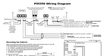
PS4350 External Battery Charger Instructions PS4350 R is an external Battery Charger for use with Panels and Specifications Stand by battery not supplied AC Trouble output Low Battery output Battery Test output Automatic shutdown to prevent deep battery Self resetting solid state over current protection eliminate the need for replacement fuses Selectable battery charging rates 400mA 700mA or Transformer supplied 16Vac 80VA Output 400mA jumper on A B 700mA jumper B C 1.8A jumper removed AC Trouble Low Battery and Battery Test Outputs maximum switched to ground through 100W Dimensions L 83mm W 56mm H over heat sinks L 3.3 W 2.2 H over heat sinks the PS4350 Unpacking PS4350 R package includes the following parts One beige PC4055C cabinet OR one red PC4055CR 15.0 x 15.0 x 6.9 One PS4085 multi rate charger module One PT1012 transformer 16 Vac 80VA Space for one 60Ah 12 volt sealed lead acid battery included Mounting the Cabinet mounting the cabinet for the PS4350 R select a dry within 1m 3.3ft of the control panel mount the cabinet From the back of the cabinet press in the four white board stand offs into the raised mounting refer to the System Installation Manual for information on limitations regarding product and function and information on the limitations as to liability of the manufacturer Holding the cabinet in position pull all wiring into Additional Terminal Functions cabinet through the hole in the back Using the provided mounting screws and wall anchors mount the cabinet securely the wall Press the PS4085 module onto the plastic stand offs Wiring beginning to wire the unit ensure that all power transformer and battery is disconnected from the panel the wiring diagrams above for instructions Battery Charge Current the battery charge current using jumper avoid damage to the battery do not select a charge rate greater than 0.1 times the AHr rating Setting Current Applying Power all wiring is completed apply power to the control Connect the battery leads to the battery then connect AC transformer For more information on control panel specifications see the control panel Installation Do not connect the power until all wiring is that you have completed the installation and connected the wiring as shown in the diagram the PS4350 should be completely AC Fail and Low Battery trouble will now function normally section describes optional functions for PS4350 ACT terminal activates when there is an AC failure the LBT terminal activates when there is a low battery On activation these terminals energize at 50mA These outputs may be used to activate an device such as an LED or a relay to activate requiring more current ACT and LBT terminals may also be connected to a panel alarm zone to generate an alarm and to have system report the trouble condition report AC failure and low battery conditions with reporting codes connect the ACT and LBT to alarm zones The ACT and LBT terminals may be connected to a single alarm zone When so both trouble conditions will be reported with single reporting code TEST Terminal activates during the automatic battery A battery test is performed every 5 seconds During test the AC power is lowered to allow the battery to the load If the battery voltage is low the test activation is extended 40 seconds This allows panel to capture the low battery condition TEST terminal may be used to activate an indicating such as an LED An RM 1 relay may also be to the TEST terminal to switch a load into the supply during the battery test The test load should of a resistance sufficient to test the battery under the maximum load Products Digital Security Controls Ltd Flint Road Downsview Ontario Canada M3J 2J6 665 8460 Fax 416 665 7498 1 800 387 3630 in Canada 29002896 R0