DSC SG-MLR2 v1 3 - Installation Manual - English - Sur-gard SCADA Multi-Line Receiver

File Preview
Click below to download for free
Click below to download for free
File Data
| Name | dsc-sg-mlr2-v1-3-installation-manual-english-sur-gard-scada-multi-line-receiver-8914376502.pdf |
|---|---|
| Type | |
| Size | 1.77 MB |
| Downloads |
Text Preview
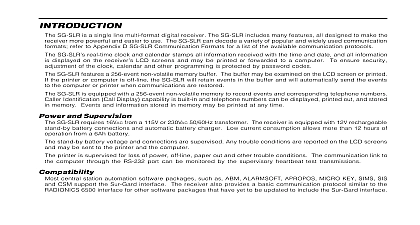
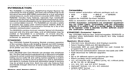
Introduction local MLR2 SCADA SCADA stands for Supervisory Control and Acquisition consists of a CPM2 module and a SCADA card module Its function is to transport alarm data from local satellite central station to the master central station This is done using linked modems like the SG M1 leased phone lines This system is specifically intended use with a point to point 300 baud Schedule 3A data line but can be used with any data line MLR2 SCADA multi line receiver is used at a master central to receive event data from and remote control one or remote receivers in distant cities The MLR2 SCADA many features all designed to make the receiver powerful and easier to use SCADA Line Cards may be added to enable the to monitor up to eight SCADA remote stations For a ULC approved system that uses backup the maximum number of SCADA remote stations seven MLR2 SCADA real time clock and calendar information received with the time and date All information displayed on the receiver LCD screens and may be or forwarded to a computer To ensure security of the clock calendar and other programming protected by password codes the remote receiver programming can be made through the for each line card to choose where data will be sent Card Options Printer Only Com Port 1 Printer Com Port 2 Printer etc allows for one or more digital dialer phone lines or compatible multiplex networks to be local while are treated as extensions of the master receiver master central station can reach outlying areas without long distance charges while the remote receiver provide services locally such as monitoring municipal Local Receiver Call and ESC mode commands entered and all local receiver troubles and restores are sent the master receiver The same commands can be sent by control from the master receiver In this way the central station has the same information and records controllability for the local receiver operation as it would a standard receiver in the master central station CPM2 Central Processing Module oversees operation the receiver Along with its built in keypad and LCD screen the CPM2 features both a printer and interface CPM2 features a 128 event nonvolatile memory buffer buffer may be examined on the LCD screen or printed the printer or computer is off line the CPM2 will retain in the buffer and will automatically send the events the computer or printer when communications are restored identification code which allows it to be identified the CPM2 Each line card in a module can store 256 printer alarm messages and 256 automation computer messages in memory Features SCADA line card has many options which are fully by sending commands from the CPM2 or by the SCADA line card push buttons Stores up to 256 printer alarm messages and 256 computer messages for subsequent display during CPM2 period Multiple alarms are sent to the computer and printer via with minimal delay Automatically goes to stand alone mode in case the CPM2 removed for program updating Built in watchdog timer continually monitors line card operation boot option to set the receiver configuration to default programming Built in storage for one current and one backup system Big Liquid Crystal Display LCD with contrast easily Built in network troubleshooting mode to examine the network or individual transmitter responses The data output to the printer computer can be examined the Liquid Crystal Display Built in buzzer is automatically silent if a successful with the CPM2 occurs as normal or if buzzer option is selected and Supervision MLR2 SCADA requires 16VAC 40VA for installations of to 6 lines and 75VA for installations of more than 6 lines a 115V or 230 VAC 50 60 Hz transformer The receiver equipped with 12V rechargeable standby battery and an automatic battery charger standby battery voltage and connections are supervised Line Cards are also continuously supervised to ensure communication with the CPM2 Any trouble are reported on the LCD screens and may be to the printer and the computer printer is supervised for loss of power off line paper and other trouble conditions The communication link to computer through the RS232 port can be monitored by supervisory test transmissions SIMS SIS MICRO KEY SMS station automation software packages such as ABM CSM ALARMSOFT MAS APROPOS the Sur Gard interface The receiver also provides basic communication protocol similar to the RADIONICS interface for other software packages that have yet to updated to include the Sur Gard interface main function of each SCADA line card is to receive store alarm data from the local satellite receivers and their alarms to the CPM2 SCADA module contains 2 line cards In the event of failure to communicate with the CPM2 each line card is of functioning independently by manual interaction the central station operator Each line card has its own Outputs CPM2 features some switched negative outputs One labelled has a corresponding LED on the front panel the factory default programming slowly the OPTION LED when the output is Switched negative outputs are also provided for Acknowledge and Trouble LEDs 1 Quick Start Receiver Setup and Operation Programming unpack the receiver and inspect for shipping If there is any apparent damage notify the carrier to Operation Bench Testing is suggested that the receiver be tested before actual Becoming familiar with the connections and setup the unit on the work bench will make final installation straightforward following items are required 16VAC transformer 40VA to 75VA 1 modified telephone cable 1 25 pin cable see diagram to the following sections of this manual for an overview the operation of the SCADA Receiver Line Card and the Central Processing Module Up Sections 3 6 SCADA Operating Mode Section 7 CPM2 and Display Information and Display Start up the receiver is to be used with a computer and central automation software refer to section 7.10 Computer Interface on page 23 power is applied the receiver will beep and will indicate or more trouble conditions on the LCD message screen the flashing ACK button to silence the buzzer If is no computer or printer connected a trouble message be displayed on the CPM2 LCD and the light will Press the ACK button to silence the CPM2 buzzer with Default Program master ID password is any changes to the factory default programming receiver operates as follows If a computer is not connected press the ACK button the CPM2 module to silence the buzzer The time date of the Acknowledgment will be printed 1 Direct Connect Testing Wiring Diagram 2 SG SCADA Cold Boot and Changing the Line Card Number Each time you change update the Program by replacing the Program EPROM the operation should be performed Otherwise the system will not work properly line card has a program enable switch situated on circuit board solder side accessible when the module partially slid out of the card cage a small flat blade is required to operate this switch SELECT is pressed after a SCADA Cold was performed the line card number will set at by default ACK or SELECT to scroll the line card number up down The allowed range is 01 to 0E for a maximum 14 cards polled by one CPM both ACK and SELECT to get out this mode and display