DSC SG-MLRV-A - Installation Manual - English - Sur-gard Single-Line Downlook Module

File Preview
Click below to download for free
Click below to download for free
File Data
| Name | dsc-sg-mlrv-a-installation-manual-english-sur-gard-single-line-downlook-module-6175940382.pdf |
|---|---|
| Type | |
| Size | 725.01 KB |
| Downloads |
Text Preview
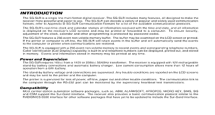
Introduction MLRV A is a single line video receiver module designed to add Downlook video capabilities to the Sur Gard Digital Receiver The MLRV A Module may be connected to any DRL2A Line Card installed in the Receiver In its maximum configuration the MLR2 DG Receiver can monitor up to 14 digital lines or a of MLRV A Modules and digital lines MLRV A via the DML5A backplane provides for two video outputs a simple coaxial output to a video monitor a video data bus output for PC connection The DLGB Downlook grabber board and the PSA software must used for PC connection Your Receiver following components are used to add Downlook Video capabilities to the MLR2 DG Receiver Video Recevier Module Card Cage accommodates one DRL2A Line Card and two MLRV A Video Modules Card Cage accommodates four MLRV A Video Modules Card Cage accommodates two DRL2A Line Cards these guidelines when adding MLRV A Modules to the MLR2 DG Receiver If several receiver lines are available but only one MLRV A Module is to be used it is recommended the be connected to the last line or on a line by itself Two MLRV A modules may be used to provide cid 147 roll over cid 148 if the first telephone line is busy for example if the MLRV A is busy another call would be processed by the second MLRV A With an MLRV A module connected the DRL2A Line Card will still be able to receive non video accounts it is recommended the number of non video accounts be limited for DRL2A Line Cards with MLRV Modules attached to reduce the possibility of a busy line MLRV A Options video display and operational options on the MLRV A are programmed with two sets of switches found the module Program these options before installing the MLRV A Module in the card cage the Module Be sure to observe proper anti static precautions when working with the MLRV A Module Set Set Receiver as viewed from the side location of programming switches the MLRV A Programming Switches the instructions below Two sets of DIP switches can be accessed through the open side of the MLRV A Module Set the switches Set 1 through 3 On Screen Display Times Set 1 and 2 Factory Test Switches switches are for factory testing only time and date display time and date display 5 Not Used 6 PAL NTSC Select OFF OFF OFF N N N N N OFF N N N N N N N display second display second display second display second display second display second display always on screen 4 On Screen Time and Date N N N 5 Display Text with Outline Option 6 Account Number Flash Option text with black outline text without outline Number does not flash Account Number 7 Sounder Option enabled disabled N 8 Account Number Display Size N Account Number Account Number 3 Communications Text Option N information not displayed communications text from DRL2A 4 Factory Test switch is used for factory testing only N Video Selected Video Selected 7 Relay 1 Option 1 will not activate 1 activates on alarm for recording N 8 8 second Image Display Option N clears after last image is image remains on screen 8 seconds Mounting Screws Insert the four black plastic collars in the four mounting holes in the MLRV A faceplate Insert the four faceplace screws into the collars the MLRV A in the Receiver Rack Slide the MLRV A Module into the Receiver Rack ensuring the connector on the back of the unit engages the on the DML5A Circuit Board secured at the back of the rack With the MLRV A in place secure the unit with the four faceplate screws Receiver Configurations MLRV A Module draws 220 mA dc while each Line Card Module draws 150 mA The total combined draw for all modules must not exceed 1.2 A dc for use with a 75 VA transformer and battery backup or 5 dc for use with a 175 VA transformer and an UPS To determine the transformer minimum VA rating the user calculate the total current for their system The Receiver Connections the following connections between the DML5A Circuit Boards and the DML2A DML5A DML5A N G N G Wire Connections the DML5 A circuit boards to the DML2A as shown in the wiring diagram Output Connection VCN1 on the DML5 A provide video output for use with a monitor or recording device VCN1 provides video output with on screen display of alarm information a video monitor or recording device with 75ohm impedence to VCN1 the MLR2 DG Receiver the following options in the MLR2 DG Receiver 4E 5E DWNLK BURST As Outputs 1 NC1 NO1 and C1 Terminals 1 will activate for several seconds after data is received from the DRL2A Module This relay may be used to time lapse video recording equipment 2 NC2 NO2 and C2 Terminals 2 will be activated for as long as video images are received by the MLRV A Module This relay may be to activate video recording equipment 3 NC3 N03 and C3 Terminals 3 will activate momentarily after each video image is received This relay may be used with a video or printing device Information MLRV A can advise of problems encountered during the receipt of video information and in the serial between the MLRV A and the DRL2A The MLRV A can indicate errors using the sounder and display messages If the sounder or on screen display functions are disabled the error messages will be indicated Indications Sounder long tones short tones long 2 short tones long 2 short tones long 3 short tones long 4 short tones data timeout data transmission is too long too early data transmission is too short too long Error Stop byte error Error String length error Error Parity error Indications On Screen Display 1 cid 148 2 cid 148 3 cid 148 4 cid 148 5 cid 148 syncpulse from alarm transmitter transmission too long without sync transmission too short with sync data video present at DLM 4 Connection DML5 A Video port must be connected to a Listed Video Equipment monitor The monitor shall be located in same room as the receiver Warranty Ltd warrants that for a period of twelve months from the date of purchase the product shall be free defects in materials and workmanship under normal use and that in fulfilment of any breach of such Sur Gard Ltd will at its option repair or replace the defective equipment upon return of the equipment its repair depot This warranty applies only to defects in parts and workmanship and not to damage incurred shipping or handling or damage due to causes beyond the control of Sur Gard Ltd such as lightning voltage mechanical shock water damage or damage arising out of abuse alteration or improper of the equipment foregoing warranty shall apply only to the original buyer and is and shall be in lieu of any and all other whether expressed or implied and of all other obligations or liabilities on the part of Sur Gard Ltd Sur Ltd neither assumes nor authorizes any other person purporting to act on its behalf to modify or to change warranty nor to assume for it any other warranty or liability concerning this product Security Systems Ltd recommends that the entire system be completely tested on regular basis despite frequent testing and due to but not limited to criminal tampering or electrical disruption it is for this product to fail to perform as expected Compliance Statement equipment has been tested and found to comply with the limits for a Class A digital device pursuant to Part 15 of the FCC Rules These limits are to provide reasonable protection against harmful interference in a commercial environment This equipment generates uses and can radiate frequency energy and if not installed and used in accordance with the instruction manual may cause harmful interference to radio communication of this equipment in a residential area is likely to cause harmful interference in which case the user w