DSC SG-SLR v1 2 - Installation Manual - English - Sur-gard Single Line Receiver

File Preview
Click below to download for free
Click below to download for free
File Data
| Name | dsc-sg-slr-v1-2-installation-manual-english-sur-gard-single-line-receiver-3251087964.pdf |
|---|---|
| Type | |
| Size | 895.95 KB |
| Downloads |
Text Preview
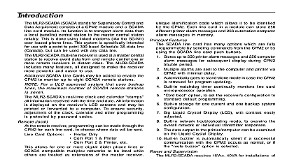
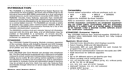
INTRODUCTION SG SLR is a single line multi format digital receiver The SG SLR includes many features all designed to make the more powerful and easier to use The SG SLR can decode a variety of popular and widely used communication refer to Appendix D SG SLR Communication Formats for a list of the available communication protocols SG SLR cid 146 s real time clock and calendar stamps all information received with the time and date and all information displayed on the receiver cid 146 s LCD screens and may be printed or forwarded to a computer To ensure security of the clock calendar and other programming is protected by password codes SG SLR features a 256 event non volatile memory buffer The buffer may be examined on the LCD screen or printed the printer or computer is off line the SG SLR will retain events in the buffer and will automatically send the events the computer or printer when communications are restored SG SLR is equipped with a 256 event non volatile memory to record events and corresponding telephone numbers Identification Call Display capability is built in and telephone numbers can be displayed printed out and stored memory Events and information stored in memory may be printed at any time and Supervision SG SLR requires 16VAC from a 115V or 230VAC 50 60Hz transformer The receiver is equipped with 12V rechargeable battery connections and automatic battery charger Low current consumption allows more than 12 hours of from a 6Ah battery stand by battery voltage and connections are supervised Any trouble conditions are reported on the LCD screens may be sent to the printer and the computer printer is supervised for loss of power off line paper out and other trouble conditions The communication link to computer through the RS 232 port can be monitored by the supervisory heartbeat test transmissions central station automation software packages such as ABM ALARMSOFT APROPOS MICRO KEY SIMS SIS CSM support the Sur Gard interface The receiver also provides a basic communication protocol similar to the 6500 interface for other software packages that have yet to be updated to include the Sur Gard interface 1 Overview Caller Identification Call Display ability Non Volatile RAM for programming and event buffer Communication Formats 3 1 3 1 extended 4 1 4 2 formats with or without Checksum 10 14 20 or 40 baud 4 1 4 2 4 3 and 4 3 DTMF formats with Checksum Optional Formats 3 2 with Baud Rates from 10 to 40 ACRON DTMF format Contact ID DTMF format Super Fast or High Speed DTMF format DTMF 4 1 Express format optional DTMF 4 2 Express format FBI Super Fast format Radionics Modem II format Scantronics DTMF format SIA level 1 and 2 110 and 300 baud tonal and data acknowledge with and without separators on SG SLR for ring simulation Large easy to read 2 line 16 characters per line Liquid Crystal Display LCD screens Plain language message display capability 256 event memory buffer Real time clock SG SLR features multiprocessor with 16 bit microcontroller 1 parallel printer port 1 serial RS 232 port Programmable serial port configuration Wait for Acknowledge Time Baud Rate Data Bits Parity Programmable system functions Computer and printer computer only computer with printer as stand by and printer only Fast transmission of multiple alarms to the computer and printer to ensure operator cid 146 s quick response Continuous verification of the computer receiver link with the heartbeat function 3 switched negative programmable outputs for future use Outputs on SG SLR for Acknowledge Buzzer Line fault Ring on line Tape recorder AC loss detection and stand by battery supervision Low battery detection and automatic low battery disconnect to prevent deep discharge damage to battery Operator acknowledge option Telephone line supervision Optional formats can be selected through the keypad SINGLE LINE RECEIVER Information SG SLR 16 bit microcontroller running at 16MHz allow the system to quickly and efficiently execute several tasks the same time The use of a unique menu display system enhances the system cid 146 s ease of use for the operator and system configuration and programming simple and efficient Several diagnostics modes are available to assist operator in troubleshooting and maintenance response Multi tasking allows the receiver to perform functions that might otherwise be delayed by a slow computer 256 event printer alarm message buffer 256 event computer alarm message buffer LCD contrast easily adjusted Cold Boot option allows easy installation of default configuration Serial port COM1 features LED indicators for Transmit Tx and Receive Rx functions Available COM1 baud rates 64 110 150 300 600 1200 2400 4800 9600 19200 COM1 Data bits 7 8 or 9 COM1 Parity Even odd or none COM 1 Stop Bits fixed at 1 Built in Serial Communication Diagnostic Mode for COM1 The technician can test the communication with the station computer and monitor what is being transmitted to and from the receiver and computer Three programmable outputs Buzzer mute option for system testing System menu for easy programming and diagnostics 3 FEATURES FOR SG SLR SOFTWARE VERSION 1.20 Format 1.20 can now receive the SIA FSK level 2 To allow the receiver to send the information on the RS 232 serial port the new Option 35 has to be enabled space character has been added to the event codes selection in Options 25 to 27 audio support Printer Library Contact ID format will print the plain English words along with the alarm code received START Setup and Operation Without Programming unpack the receiver and inspect for shipping damage If there is any apparent damage notify the carrier Testing is suggested that the receiver be tested before actual installation becoming familiar with the connections and setup the unit on the work bench will make final installation more straightforward following items are required 16V transformer 12V 4 to 24 Ah rechargeable battery gell type 1 telephone line One or more dialers or digital dialer control panels connection testing without the use of telephone lines is possible by using the ring simulator switch input connections the back of the receiver Dialers and control panels using an optocoupler phone line interface will require a connection providing a DC current for direct connection testing refer to the illustration below Up power is applied the receiver will beep and will indicate one or more trouble conditions on the LCD message If the SG SLR has no telephone line connected the receiver will beep and the cid 147 ALARM cid 148 light will FLASH the flashing SELECT button to silence the buzzer If there is no computer or printer connected a trouble will be displayed on the SG SLR LCD and the cid 147 ACK cid 148 light will FLASH Press the SELECT button to silence SG SLR buzzer with Default Program any changes to the factory default programming the receiver operates as follows The master ID password is Answers incoming calls on the first ring Sends dual tone as the first handshake 1 2300 Hz as the second handshake 2 1400 Hz as the third handshake 3 SIA FSK tone as the fourth handshake 4 2000 Hz as the fifth handshake 5 1600 Hz as the sixth handshake 6 Modem II as the seventh handshake 7 Signals received will be displayed on the LCD as they are received The signals are then sent to the parallel printer computer connected to serial port COM1 The default event codes described in the cid 147 SG SLR Library Decoding Event Codes Table cid 148 will be used with the Sur Gard RS 232 Communication Protocol to send signals to the if connected a computer is not connected press the SELECT button on the SG SLR module to silence the buzzer The time date of the Acknowledgment will be printed Connect Testing Wiring Diagram Shown with P 16LC Control Panel 5 the Receiver Connections LCD screen on the receiver are designed to be viewed below eye level If the unit must be mounted where the are above eye level angle the unit downwards to improve visibility The f


