DSC VVM110 v1 0 - Installation Manual - English - PowerSeries Visual Verification Module

File Preview
Click below to download for free
Click below to download for free
File Data
| Name | dsc-vvm110-v1-0-installation-manual-english-powerseries-visual-verification-module-6248710953.pdf |
|---|---|
| Type | |
| Size | 831.71 KB |
| Downloads |
Text Preview
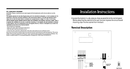
VVM110 Verification Module with PC1555MX PC5010 PC5020 Control Panels Guide This manual contains information on limitations regarding product use and function and on the limitations as to liability of the manufacturer Read the entire manual carefully of Contents Introduction 1 Basic Operation 1 Remote Look In 1 Features 2 Specifications 3 Installation Instructions 5 Programming the Control Panel 6 PGM Programming 8 Zone Programming 8 Visual Access Software Installation 6 System Requirements 8 Initial Visual Access Operation 8 Entering and Connecting to a New Site 8 System Checkout 9 Troubleshooting 10 Appendix A Direct Connection to Laptop PC Computer 12 Appendix B Initial Visual Access Operation 13 Appendix C Pan Tilt Zoom 15 Introduction Video Verification Module VVM110 captures and stores video images ME JPEG for transmission to a central station for visual verification of Images are transmitted over standard telephone lines using an internal modem The capture of images is initiated a zone violation in an associated control panel Specialized software Visual Access Software allows the user configu options including pre trigger post trigger on alarm frame capture rate and image resolution Refer to Visual Access User Guide for additional details Operation information from the 4 video inputs is initially formatted into an ME JPEG format and stored in an on board buffer video captures store only the difference data required to assemble the frames captured When the buffer is full data is continuously updated by writing the new data over the old data This process ensures that a recent history is in memory before an alarm event occurs The buffer allocated to on going storage is programmable using Access Software When an alarm event occurs the control panel calls the central station to report the alarm and signals the VVM110 via the Keybus The remaining video buffer memory is used to capture the event When the memory is filled recording of video events ceases After the central station call is completed the VVM110 takes of the phone line and calls a previously stored number for the central station that will process the video signal The video clip including the pre alarm video and the post alarm video is transmitted to the central station using the modem Central Station calling and transmission of video by the VVM110 is independant of the control panel If a subse alarm event occurs during video transmission the transmission will be termiated and the control panel seize the phone line to forward the alarm information to the central station When the call is com pleted the will resume its call to the central station and transfer the video data Contact your central station to confirm support for VVM110 Ozvision video transmission protocol Look In data can also be retrieved by accessing the module via telephone with a PC using Visual Access Software and uti the module in a streaming video mode Video Verification Module 4 baseband video inputs NTSC PAL compatible PSTN telephone connection Tip Ring Keybus interface to DSC control panels Status LEDs Green Power On indicator Red Flashes during self test Standard RS232 serial port for Euro ISDN connection PC PDA Cellphone Supports cellular GSM TDMA CDMA cellular carriers which support CSD Circuit Switch Data or HSCSD Speed Circuit Switch Data and with full duplex communication networks including Satellite and RF Pan Tilt Zoom PTZ supports ERNA VCLTP Ultrack Migvan EscBaz and DynaColor protocols On board modem controller Control Panels supported PC1555MX PC5010 PC5020 Video Verification Module Operating Temperature Range 32 to 131 0 50 Voltage 12 to 17VDC Current Draw Standby 370 mA Transmitting 490 mA Max Humidity 25 to 80 Non Condensing Resolution 128h x 100v NTSC or PAL 256h x 100v NTSC or PAL 256h x 200v NTSC or PAL 512h x 200v NTSC or PAL Color Resolution 16.8 mi llion colors with 256 gray scales On board Frame Storage 200 KBytes 1 Wiring Diagram Supply V 500mA or Equivalent Video Verification Module Panel PC1555MX PC5010 PC5020 VDC Video Input x 75 Switch Board Off Line LED power on LED status BLK YEL GRN Tip R1 T1 BLK YEL GRN 232 Male Tip Insert Stand off into cabinet hole in the desired location Position circuit board mounting holes standoffs Press firmly on board snap in place Line Appendix A direct connection PC Laptop Appendix B connection to Installation Instructions Video Verification Module unit in the control panel enclosure using the hardware provided see Figure 1 R 1 and T 1 on the Control panel to the VVM110 module Ensure that all plugs and jacks meet the dimension tolerance and plating requirements of 47 C F R Part 68 F For proper operation there must not be any additional equipment connected between the control and the telephone company facilities e g fax machines the video cables from the CCTV cameras to the BNC connectors The DIP Switch is set for direct connection of CCTV cameras to the unit down If the CCTV cameras are con in parallel to other devices e g VCR Monitors Set the associated DIP switch to the UP position to correct termination that the designated trigger zones on the control panel are installed the Keybus from the control panel to the VVM110 module using 22AWG 5mm quad twisted two pair a 12 VDC 500 mA power supply to Power In terminals on the VVM110 Ensure that the correct polarity is observed when connecting to the power source power The negative power input negative power output circuit common and unit chassis are tied together in the Video Verification Module the Keybus from the control panel to the VVM110 module using 22AWG 5mm quad twisted two pair system Programming the Control Panel Video Verification Module Programming Refer to the associated Control Panel Installation Manual Installer Programming Section 10 Set PGM 03 output to 13 Kissoff PGM attributes Section 503 must be programmed with the default settings Refer to the Installation Manual Programming activation of cameras does not require any special programming at the panel The linking of