DSC WLS904 v4 3L - Installation Manual - English - Wireless Passive Infrared Motion Detector

File Preview
Click below to download for free
Click below to download for free
File Data
| Name | dsc-wls904-v4-3l-installation-manual-english-wireless-passive-infrared-motion-detector-5910476382.pdf |
|---|---|
| Type | |
| Size | 696.31 KB |
| Downloads |
Text Preview
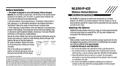
Battery Installation This system is designed to work with Eveready Alkaline Energizer Do not install any other type The reliability of the security system on its batteries and name or generic brand batteries may not pro the best quality and dependability Use fresh batteries Most batteries have a before date printed on their or on the batteries themselves Buy batteries that have a before of two years or more from your purchase date When disposing of used batteries follow the and precautions printed on the Many cities and communities have sites or services for used household Contact your municipal offices for on the disposal of used batteries the motion detector from its mounting by holding the sensor by its sides and up Install four fresh Eveready Alkaline AAA batteries Be sure to insert the in the proper orientation Replace the on its mounting plate making sure it into place After the batteries are the detector will take 60 seconds to up During this time the LED will flash Compliance Statement Changes or modifications not expressly approved by Digital Security Controls Ltd could void your authority use this equipment equipment generates and uses radio frequency energy and if not installed and used properly in strict accordance with manufacturer instructions may cause interference to radio and television reception It has been type tested and found comply with the limits for Class B device in accordance with the specifications in Subpart of Part 15 of FCC Rules are designed to provide reasonable protection against such interference in any residential installation However there no guarantee that interference will not occur in a particular installation If this equipment does cause interference to tele or radio reception which can be determined by turning the equipment off and on the user is encouraged to try to cor the interference by one or more of the following measures Re orient the receiving antenna Relocate the alarm control with respect to the receiver Move the alarm control away from the receiver Connect the alarm control into a different outlet so that alarm control and receiver are on different circuits necessary the user should consult the dealer or an experienced radio television technician for additional suggestions The may find the following booklet prepared by the FCC helpful to Identify and Resolve Radio Television Interfer Problems This booklet is available from the U S Government Printing Office Washington D C 20402 Stock 004 Warranty Security Controls Ltd warrants that for a period of twelve months from the date of purchase the product shall be of defects in material and workmanship under normal use and that in fulfilment of any breach of such warranty Digital Controls Ltd shall at its option repair or replace the defective equipment upon return of the equipment to its repair This warranty applies only to defects in parts and workmanship and not to damage incurred in shipping or handling damage due to causes beyond control of Digital Security Controls Ltd such as lightning excessive voltage mechanical water damage or damage arising out of abuse alteration or improper application of the equipment foregoing warranty shall apply only to the original buyer and is and shall be in lieu of any and all other warranties whether or implied and of all other obligations or liabilities on the part of Digital Security Controls Ltd This warranty contains entire warranty Digital Security Controls Ltd neither assumes nor authorizes any other person purporting to act on its to modify or to change this warranty nor to assume for it any other warranty or liability concerning this product no event shall Digital Security Controls Ltd be liable for any direct indirect or consequential damages loss of anticipated loss of time or any other losses incurred by the buyer in connection with the purchase installation or operation or of this product 1999 Digital Security Controls Ltd Flint Road Downsview Ontario Canada M3J 2J6 416 665 8460 Fax 416 665 7498 Tech Line 1 800 387 3630 in Canada 29003210 R1 Motion Detector INSTRUCTIONS Version 4.3L Motion Detector should be located so that it provides optimal coverage of the area Refer to Changing Motion Detector Lenses below for information the four lenses available for the WLS 904 Motion Detector When locating Detectors observe the following For the Wall to Wall Corridor and Curtain Lenses the Mounting Height should 6 10 ft 2 3 m from the floor The nominal mounting height is 7.5 ft 2.3 m For the Pet Alley Lens only the Mounting Height should be 4 5 ft 1.2 1.5 m from floor Do not aim the detector at reflective surfaces such as mirrors or windows This distort the coverage pattern or reflect sunlight directly onto the detector locations where the detector may be exposed to direct or reflected sunlight Avoid locations that are subject to direct air flow such as near an air duct outlet Do not locate the detector near sources of steam or oil vapor such as a stove or fryer Do not obscure the Detector coverage pattern with large objects within the area If you can see the detector it can see you For indoor use only Dead zone 6 cm No detector should be mounted without first performing a module test to determine that it is in range of the wireless receiver the Placement Test instructions in the Instruction Sheet for your or in the installation manual for your system a location has been determined remove the plastic from the mounting holes locate the backplate on the wall and mark screw locations It is suggested that anchors be used for all screw locations Secure the backplate to the wall and secure the enrolled Detector to its backplate a WLS 904 the back of the PIR housing there will be two serial numbers a five digit num and a six digit number Please refer to your receiver installation manual for on which serial number should be enrolled NOTENOTE If using a WLS900 you must use the five digit serial number Motion Detector Lenses Motion Detector is supplied with the Wall lens three additional lenses are avail for the WLS 904 Motion Detector The on the next page illustrate the range and patterns of each lens change the lens first open the Motion by removing the screw in the bottom the battery compartment With the screw pull the back of the detector away the front case The coils and antenna on the Motion Detector circuit board are very components precisely adjusted for maximum performance Do touch the coils or antenna Even minor distortions can affect the per of the Motion Detector the lens holder by pressing down on the top of the holder and pulling the away from the case When installing the new lens ensure the grooved sur faces the interior of the case and the notches on the lens face the bottom of case Replace the lens holder by snapping it back into place the motion detector by first engaging the clips on the bottom of the Close the case and then secure the case with the screw in the bottom of the compartment Motion Detector Sensitivity motion detector features Fast and Slow modes which are set on jumper J1 J1 is set at the factory for the Fast detec mode In a normal operating environment setting provides the best detection certain environments where rapid air move heaters and other variables present prob use Slow detection mode to stabilize the diagram on the right shows the jumper loca To change the setting from Fast to Slow the jumper over one pin as shown in the Refer to the PC5132 and PC5010 UL ULC For UL ULC the WLS904 is used on entry or exit zones the entry delay must not be than 39 seconds and the exit delay must not be longer than 54 Traffic shutdown Mode prolong battery life the motion detector uses a feature called High Traffic Shut When motion is detected the device will transmit to the receiver and will then down for three minutes If motion is detected again during the shutdown time unit will not transmit the event to the receiver The detector will thus remain in shutdown mode until three minutes after the first motion detected was transmit The detector will transmit detected motion every three minutes High Traffic Shutdown Mode affects testing the motion detector in two ways When performing the module plac