DSC WLS912L - WLS922L - Installation Manual - En-Fr-Sp-Po - Wireless Glassbreak Detector

File Preview
Click below to download for free
Click below to download for free
File Data
| Name | dsc-wls912l-wls922l-installation-manual-en-fr-sp-po-wireless-glassbreak-detector-9053248617.pdf |
|---|---|
| Type | |
| Size | 1.34 MB |
| Downloads |
Text Preview
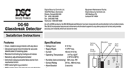
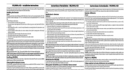
WLS912L WLS922L Wireless Glassbreak Detector INSTRUCTIONS Models WLS912L 433 WLS922L 433 WLS912L and WLS922L are battery operated glassbreak sensors to detect the sound produced by the shattering of framed Equipped with an RF transmitter the WLS912L WLS922L estab a supervised one communications link with the alarm con panel The WLS912L WLS922L uses Dynamic Signal Processing provide accurate detection of plate laminated wired and tempered types while rejecting common false alarm sounds Operating Voltage 3.0V Batteries Two 3V lithium Low Battery level 2.65V Battery capacity 1500mAh Operating Temperature 0 50 32 122 Dimensions 135 x 60 x 35mm Operating Humidity 5 95 RH non condensing Weight 130g Input rating 3VDC max 0.2 mA Detection Range Type Thickness Minimum Glass under US Patent 5,675,320 2 1 1 4 6 mm 18 NOT 46cm 30cm panels and receivers RF5132 433 RF4164 433 RF5108 TR5164 433 SCW9045 47 433 SCW9055 SCW9067 433 PC9155 433 Guidelines and Installation Use fresh batteries Most batteries have a before date printed on packaging or on the batteries themselves Buy batteries that have before date of two years or more from your purchase date When disposing of used batteries follow the instructions and precau printed on the batteries Many cities and communities have sites or services for used household batteries Contact your offices for information on the disposal of used batteries Do not mix old and new batteries Dispose of any batteries promptly keep away from children Use only Energizer Lithium EL123AP Tekcell CR123A Panasonic or Duracell Ultra 123 lithium battery Use of any other battery may a risk of fire or explosion The cell used in this device may cause a fire or chemical burn if mistreated Do not recharge disassemble heat above 100 or incinerate WLS912L 433 WLS422L 433 is UL listed for Residential Burglary Commercial Burglary applications in accordance withe the follow standards UL639 UL1023 UL1610 install batteries L X W 12 Remove the detector from its mounting plate If unmounted hold the by its sides and push down on the top end of the mounting as shown in the diagram If mounted press the detector in the shown in the diagram Install the batteries positive side first with the correct polarity as in the diagram the Dip Switches detector has user selectable dip switch settings as shown Switch 1 Not Used Switch 2 Level 1 Level 2 Detection is a sensitivity selection dip switch which may be used to optimize alarm immunity for certain acoustic environments detector is factory set for Level 1 detec Dip Switch 2 OFF This is the high sensitivity setting for the detector and be suitable for most applications smaller rooms with a significant number sound reflective surfaces such as bath kitchens entrances etc Level 2 Dip Switch 2 ON provides sensitivity which may be more appropriate a Mounting Location detector is unidirectional and picks up sound aimed directly into the and center of the detector Coverage is measured from the of the detector to the point on the glass farthest from the detector for optimizing detection and avoiding false alarms For optimum protection the detector should have a direct line of sight the protected glass Window coverings will absorb sound from the shattering glass In these mount the detector as close as possible to the protected glass on an adjacent wall the ceiling or behind the window covering if The detector should be mounted at least 1.8m 6 feet off the ground Do not mount the detector on the same wall as the protected glass Avoid installation near noise sources such as speakers or other which produce sounds continuously Do not install the detector beyond the maximum recommended range if the AFT 100 simulator shows additional range future changes room acoustics could reduce the range Application on 24 hour loops should be avoided unless the location is Test false alarm immunity by generating any sounds in the room which occur when the alarm system is armed Test the detector thoroughly for proper placement using the AFT Glassbreak Simulator Other simulators may trip the unit but will not accurate test results the detector the following to ensure that the is mounted in best possible loca Test Place the detector in pressing on the tab on the base plate as shown The LED blinks periodi to indicate that it is operating in test mode You can end the test by momentarily pressing the tab on the base plate Test mode will automatically after 10 minutes Use double sided tape to temporarily mount the detector in the selected The detector will not respond to the glassbreak simulator unless test mode operation has been enabled At the window to be protected test the detector using the AFT 100 Simulator The AFT 100 Glassbreak Simulator gener plate or tempered glass sounds Use the plate glass setting if are unsure of the glass type Observe the following when testing detector If the WLS912L WLS922L detects the sound generated by the AFT three times in a row the detector is in a good location If the does not respond each time relocate the detector and the test If the window is covered by drapes or blinds place the AFT 100 tes behind the closed window coverings and activate it If the drapes reliable detection we suggest that the detector be mounted the drapes either on an adjacent wall or on the ceiling If there are multiple windows or one large window activate the tes at the furthest point on the glass from the detector Test a Module Placement Test to ensure that the selected location is in of the wireless receiver see the Placement Test instructions in the instructions for your receiver Press and hold the test mode tab for 5 seconds Release the test mode tab The keypad displays the test result the WLS912L WLS922L serial numbers are located on the back of the detector a five digit and a six digit number Please refer to your receiver installation for information on which serial number should be used the Detector a suitable location is found mount the WLS912L WLS922L Remove the mounting plate the detector At the selected mounting loca place the mounting plate the wall with the tab facing or to the right or on the Mark the screw loca Wall anchors should be for all screw locations Secure the backplate to the Slide the detector onto its back Repeat the AFT 100 tester to proper operation For UL Listed installations use provided screw to secure the device the mounting plate mounting on wall tab should either down to the right D de bris de verre D disponibles WLS912L 433 WLS922L 433 WLS912L WLS922L est un d de bris de verre fonctionnant sur Il est con pour d le bruit produit par le bris du verre encadr d de fr radio le WLS912L WLS922L lien de communication unidirectionnel avec le contr du syst WLS912L WLS922L utilise le traitement de signal dynamique Signal Processing afin d une d pr de bris verre de type vitrage verre feuillet verre arm et verre tremp tout en les bruits qui provoquent fr des fausses alarmes Voltage de fonctionnement 3.0V Deux piles du lithium 3V Niveau pile faible 2.65V Capacit de la pile 1500mAh Temp de fonctionnement 0oC 50oC 32o F 122oF Dimensions 135 x 60 x 35mm Humidit de fonctionnement 5 95 RH non condensing Poids 130g Courant nominal 3VDC max 0.2mA de d maximum par le brevet US Patent