DSC WS8904 INIS EN-FR-SP fm

File Preview
Click below to download for free
Click below to download for free
File Data
| Name | dsc-ws8904-inis-en-fr-sp-fm-1705249683.pdf |
|---|---|
| Type | |
| Size | 1.02 MB |
| Downloads |
Text Preview
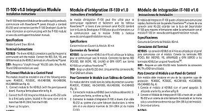
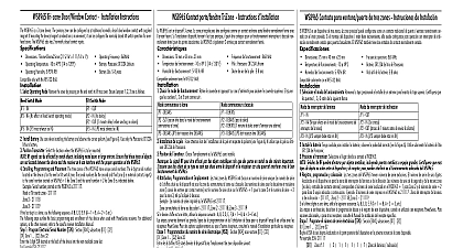
WS8904 Installation Instructions d WS8904 de Instalaci WS8904 Installation Manual shall be used in conjunction with the Installation Manual of the DSC RF5132 868 MHz wireless receiver and control panel which this device is intended to be used WS8904 motion detector should be located so that it provides optimal coverage of the intended area Refer to Changing Motion Detector below for information on the four lenses available for the WS8904 Motion Detector the Detector locating motion detectors observe the following for Wall to Wall Corridor and Curtain Lenses the mounting height should be 6 10 ft 2 3m the floor The nominal mounting height is 7.5 ft 2.3m For the Pet Alley Lens only the mounting height should be 4 5 ft 1.2 1.5m from the the following to avoid false alarms Do not aim the detector at a stairwell to which a pet has access Do not place furniture or objects higher than 3ft 0.9m which a pet can climb onto e g a cat on a couch closer than 6ft 1.8m from the manuel d doit utilis en conjonction avec le manuel d du r sans fil DSC RF5132 868 MHz et du panneau contr pour lequel ce dispositif a con d de mouvement doit install de mani offrir la couverture optimale de l d Pour des renseignements sur les quatre disponibles pour le d de mouvement WS8904 consultez Changement de lentilles pour d de mouvement ci dessous du d les lentilles mur mur couloir et rideau le dispositif doit install une hauteur de 2 3 m 6 10 pieds du sol La hauteur nominale pour du dispositif est de 2,3 m 7,5 pieds Pour la lentille all pour animaux domestiques seulement le dispositif doit install une hau de 1,2 1,5 m 4 5 pieds un emplacement qui offrira la couverture requise et permettra au d d install une hauteur minimum de 1,95m 6,5 pi et max de 3m 10 pi 2,3 m 7,5 pi recommand Tenez compte des suivants pour les fausses alarmes Ne placez pas le d face un escalier auquel un animal domestique a acc Ne placez pas de meuble ou d d hauteur de plus de 0,9 m 3 pi sur lequel un animal domestique peut grimper par ex un chat sur un Mount the detector flat on a wall or in a corner Do not angle it downwards or use mounting brackets with this detector when it is used in con moins de 1.8 m 6 pi du d Do not aim the detector at reflective surfaces such as mirrors or windows as this may distort the coverage pattern or reflect sunlight directly onto utilis et que des animaux domestiques sont pr Installez le d plat sur un mur ou dans un coin Ne l pas vers le bas et n pas de support de montage lorsque ce d directamente al detector with pets detector Avoid locations that are subject to direct high air flow such as near an air duct outlet Do not locate the detector near sources of moisture such as steam or oil Do not limit the coverage by large obstructions in the detection area such as plants or cabinets For indoor use only non hazardous locations No detector should be mounted without first performing a module placement test to determine that it is in range of the wireless receiver the Placement Test instructions in the Instruction Sheet for your receiver or in the Installation Manual for your system a location has been selected remove the plastic from the mounting holes and locate the backplate on the wall and mark screw locations is suggested that wall anchors be used for all screw locations Secure the backplate to the wall and then secure the enrolled detector to its Use only backplates marked as Using any other backplates will result in the tamper switch being broken a WS8904 the back of the PIR housing there will be a six digit number Motion Detector Lenses motion detector is supplied with the Wall to Wall lens three additional lenses are available for the WS8904 motion detector The charts on the page illustrate the range and coverage patterns of each lens change the lens first open the motion detector by removing the screw in the bottom of the battery compartment With the screw removed pull the of the detector away from the front case Remove the lens holder by pressing down on the top of the holder and pulling the holder away from case When installing the new lens ensure the grooved surface faces the interior of the case and the notches on the lens face the bottom of the Replace the lens holder by snapping it back into place Reassemble the motion detector by first engaging the clips on the bottom of the case the case and then secure the case with the screw in the bottom of the battery compartment the Motion Detector Sensitivity motion detector features Fast and Slow detection modes which are set on jumper JP1 In a normal operating environment the fast setting pro the best detection certain environments where rapid air movement heaters and other variables present problems use Slow detection mode to stabilize the detec Jumper is located at the top right under the battery bucket of the circuit board To change the setting from Fast to Slow move the jumper one pin as shown in Figure 4 Traffic Shutdown Mode prolong battery life the motion detector uses a feature called High Traffic Shutdown When motion is detected the device will transmit to the and will then shut down for three minutes If motion is detected again during the shutdown time the unit will not transmit the event to receiver The detector will thus remain in the shutdown mode until three minutes after the first motion detected was transmitted The detec will transmit detected motion every three minutes The High Traffic Shutdown Mode affects testing the motion detector in two ways performing the module placement test the unit must be tampered by removing the unit from the backplate and replacing it The placement cannot be performed by creating motion in front of the device performing a system test the unit must be left idle for three minutes before testing can be performed Once three minutes has passed create in front of the detector to see if the device is both detecting motion and transmitting to the receiver Detector Transmission Delay motion detector transmission is always delayed by 6 seconds This is necessary to prevent false alarms caused by a motion sensor transmit before a delay zone has a chance to report This 6 second delay cannot be altered or disabled Ne placez pas le d en face de surfaces r telles que des miroirs ou des fen car elles pourraient d le diagramme de ou r la lumi solaire directement sur le d les emplacements o le d pourrait expos un courant d intense comme une sortie de gaine de circulation d Ne placez pas le d pr de sources d telles que de la vapeur d ou d Ne limitez pas la couverture en pla des objets importants dans la zone de d telles que des plantes ou des armoires Pour utilisation int seulement N d aucun d avant d fait un essai de placement de module pour d s se trouve dans la port r sans fil Voir les instructions d d dans la Notice d de votre r ou dans le Manuel d de syst emplacement a trouv retirez le plastique des trous de montage placez la plaque arri sur le mur et marquez l des vis vous sugg d des ancres pour toutes les vis Fixez la plaque arri au mur puis fixez le d sur sa plaque arri Utilisez seulement une plaque arri identifi Si vous utilisez n quelle autre plaque arri vous endommag l interrupteur antisabotage d WS8904 y a un num six chiffres au dos du coffret PIR de lentilles pour le d de mouvement d est fourni avec la lentille mur mur trois lentilles suppl sont disponibles pour le d de mouvement WS8904 Les de cette page illustrent la port et le diagramme de rayonnement de chaque lentille changer la lentille ouvrez d le d de mouvement en retirant la vis au fond du r