DSC WS8965 ENG FRE-SPA

File Preview
Click below to download for free
Click below to download for free
File Data
| Name | dsc-ws8965-eng-fre-spa-3647508129.pdf |
|---|---|
| Type | |
| Size | 1.06 MB |
| Downloads |
Text Preview
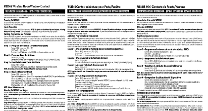
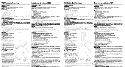
WS8965 Tri zone Door Window Contact Installation Instructions Contact porte fen TriZone Instructions d WS8965 Contacto para ventana puerta de tres zonas Instrucciones de Instalaci WS8965 is a 3 zone device The primary zone can be configured as a traditional normally closed door window contact with supplied magnet If mounting the combination is inconvenient it can be configured for normally closed tilt switch operation for overhead doors The WS8965 also has 2 normally closed inputs Dimensions 75mmx43mmx25mm 2 15 16 x 1 11 16 x 1 Operating Temperature 10 to 49 14 to 120 Operating Humidity 5 93 RH only with the RF5132 868 Select Operating Mode Remove the cover by pressing on the end notch to lift top cover Ensure Jumpers 1 2 3 are as follows Switch Mode IN NA No effect in Reed Switch operating mode Operating Frequency 868MHz Battery Panasonic CR123A Lithium Battery Life 5 8 years Switch Mode OUT IN No delay OUT 1 minute delay before sending an alarm IN JP3 must always be IN IN JP3 must always be IN Install Battery Use care when installing the battery and observe the correct polarity see Figure A Use only the Panasonic CR123A lithium battery Position Transmitter Select the location where the WS8965 is to be mounted RF signals can be affected by metal objects including metal doors or large mirrors Ensure that these types of objects are not located the device and the receiver as it can interfere with the proper operation of the WS8965 Enrolling Programming and Placement The three zones of the WS8965 have unique serial numbers The 6 digit serial number located on the is for the reed or tilt switch zone The serial numbers for the second and third zone i e external contacts inputs is the serial number located on for Zone 2 and the serial number 2 for Zone 3 as indicated below Serial number printed on the WS8965 is 211117 or Tilt switch zone 211117 2 211118 3 211119 the last digit is a letter use the following sequence A B C D E F A 1 B A 2 C etc following steps outline the basic programming and enrollment of this device when used with PowerSeries receivers For additional options or for other receivers to the specific receiver Installation Manual 1 Program Electronic Serial Number ESN Section 804 subsections 01 32 Zone 1 32 Zone 32 the 6 digit ESN located on the back of the device into the next available zone slot Example ESN 211117 1 zone 2 3 contact zone contact zone 2 Program Zone Definition Section 001 004 corresponding zone with appropriate zone type Ex Delay 01 Instant 03 etc 3 Enable Wireless Zone Attribute Section 101 132 Option 8 ON wireless zone attribute in the corresponding zone attribute section wireless devices must be tested for good signal strength from where they are positioned NOTE Test wireless device signal strength from the final mounting position 4 Module Placement Test Section 904 subsections 01 32 a transmission by moving the magnet away from the WS8965 or by activating the tilt sensor panel will sound the siren and light LED 1 or 3 to indicate the test result squawk of the siren or keypad LED 1 indicates GOOD placement squawks of the siren or keypad LED 3 indicates BAD placement the transmitter tests BAD move the transmitter and repeat the Placement Test until 3 GOOD results in a row are indicated Mounting the WS8965 the WS8965 in Reed Switch Mode Place the mounting bracket in the position determined in the Enrolling Programming Placement step Secure the bracket to the door frame using two screws provided See Figure B the sensor in place To release bracket Remove the front cover Push the tab see Figure B with a small screwdriver and slide the WS8965 down Align one end of the magnet with the notch on the side of WS8965 housing See Figure A Mount the magnet a maximum of 1 2 1.27cm from the WS8965 using the screws provided If necessary use the spacers provided See Figure C Mount magnet Open and close the door window to ensure that there is no interference NOTE Only one magnet can be used for each WS8965 The contact shall be installed so that a door or window cannot be opened than 2 inches 51 mm without causing an alarm condition the WS8965 in Tilt Switch Mode Remove Jumper 1 JP1 for switch operation For the tilt switch to be in the closed position mount the WS8965 in the vertical position with the battery located on the bottom Once the garage is open the tilt switch will activate and generate a transmission See Figure D WS8965 can be programmed to wait 1 minute after the tilt switch activates before it transmits the alarm This is useful for the garage doors which require longer delay time To program this feature remove Jumper 2 JP2 The reed switch is deactivated when using the tilt function By carefully moving the tilt switch up or down the degree of motion required to cause an alarm be adjusted Do not permanently mount the WS8965 until the Placement Test has been successfully passed WS8965 est un dispositif 3 zones La zone principale peut configur comme un contact ordinaire porte fen normalement ferm avec l fourni Si l dispositif aimant n pas pratique il peut configur pour un fonctionnement interrupteur bascule normalement ferm pour des portes basculantes Le a 2 entr par contact normalement ferm Dimensions 75 mm x 43 mm x 25 mm Temp de fonctionnement 10 49 C 14 120 F Humidit de fonctionnement 5 93 HR seulement avec le RF5132 868 Choisir le mode de fonctionnement Retirer le couvercle en appuyant sur cran d pour soulever le couvercle sup S que les cava Fr de fonctionnement 868 MHz Pile Panasonic CR123A Lithium Dur de vie de la pile 5 8 ans WS8965 es un dispositivo de tres zonas La zona principal puede configurarse como un contacto tradicional de puerta ventana normalmente cerrado con el im prove Si montaje del dispositivo im fuere inconveniente ella puede configurarse para operaci con interruptor de inclinaci normalmente cerrado para puertas basculantes El tambi tiene dos entradas de contacto normalmente cerrado Dimensiones 75 mm x 43 mm x 25 mm Temperatura de funcionamiento 10 a 49 Humedad de funcionamiento 5 93 UR solamente con el RF5132 868 Seleccione el modo de funcionamiento Remueva la tapa presionando el entalle de un extremo para levantar la tapa superior Certif que los puentes 1 Frecuencia operativa 868 MHz Bater CR123A de litio de Panasonic Vida de la bater 5 8 a 1 2 et 3 sont comme suit commutateur lame DEDANS S O aucun effet dans le mode de fonctionnement commutateur lame commutateur bascule DEHORS DEDANS pas de d DEHORS 1 minute de d avant d une alarme DEDANS JP3 doit toujours DEDANS DEDANS JP3 doit toujours DEDANS Installation de la pile Faire attention lors de l de la pile et respecter la polarit voir Figure A N que la pile au lithium CR123A de Panasonic Position de l Choisir l o le WS8965 sera install Le signal RF peut affect par des objets m tels que des portes en m ou des miroirs importants S que des de ce type ne sont pas situ entre le dispositif et le r car cela pourrait interf avec le bon fonctionnement du WS8965 Attribution Programmation et Emplacement Les trois zones du WS8965 ont chacun un num de s unique Le num de s 6 chiffres situ sur dispositif est pour la zone du commutateur lame ou bascule Les num de s pour la deuxi et troisi zone savoir les entr par contact externe le num de s situ sur le WS8965 1 pour la zone 2 et le num de s 2 pour la zone 3 tel qu ci dessous Le num de s