DSC WT4989 Operating Instructions 29007536R004
File Preview
Click below to download for free
Click below to download for free
File Data
| Name | dsc-wt4989-operating-instructions-29007536r004-9452386701.pdf |
|---|---|
| Type | |
| Size | 1.11 MB |
| Downloads |
Text Preview
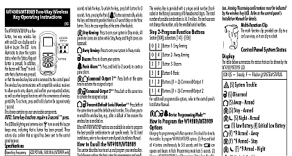
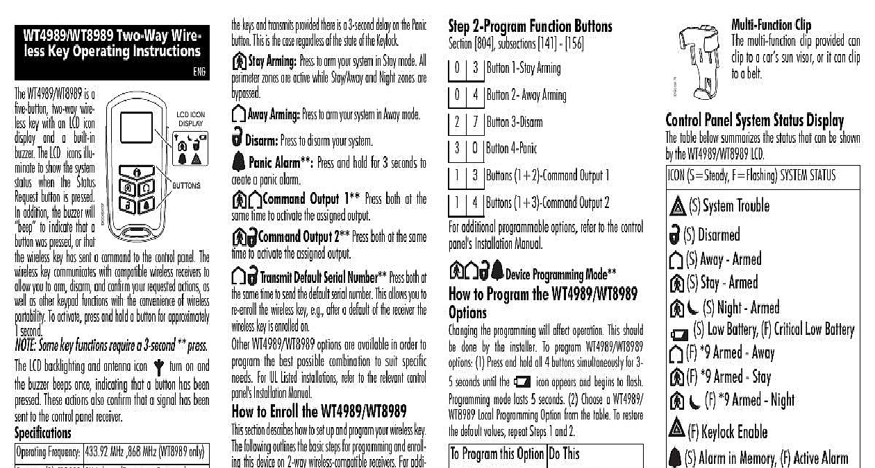
WT4989 WT8989 Two Way Wire Key Operating Instructions ICON WT4989 WT8989 is a two way wire key with an LCD icon and a built in The LCD icons illu to show the system when Status button is pressed addition the buzzer will to indicate that a was pressed or that wireless key has sent a command to the control panel The key communicates with compatible wireless receivers to you to arm disarm and confirm your requested actions as as other keypad functions with the convenience of wireless To activate press and hold a button for approximately second Some key functions require a 3 second press LCD backlighting and antenna icon turn on and buzzer beeps once indicating that a button has been These actions also confirm that a signal has been to the control panel receiver Frequency 433.92 MHz 868 MHz WT8989 only CR2032 3V Lithium Panasonic Energizer Life years under typical use LxWxH 75mm x 40mm x 16mm Receiv PC9155D 433 868 PC9155G 433 868 868 for WT4989 is UL ULC listed This equipment shall be used in an envi that provides the pollution degree max 2 in locations ONLY Button Functions Request Press this button for 1 second to view the panel system status via the LCD icons Press and hold both at the same time for 3 to lock the keys To unlock the keys press both buttons for 3 Note pressing the Panic button automatically unlocks keys and transmits provided there is a 3 second delay on the Panic This is the case regardless of the state of the Keylock Stay Arming Press to arm your system in Stay mode All zones are active while Stay Away and Night zones are Away Arming Press to arm your system in Away mode Disarm Press to disarm your system Panic Alarm Press and hold for 3 seconds to a panic alarm Output 1 Press both at the time to activate the assigned output Output 2 Press both at the same to activate the assigned output Default Serial Number Press both at same time to send the default serial number This allows you to the wireless key e g after a default of the receiver the key is enrolled on WT4989 WT8989 options are available in order to the best possible combination to suit specific For UL Listed installations refer to the relevant control Installation Manual to Enroll the WT4989 WT8989 section describes how to set up and program your wireless key following outlines the basic steps for programming and enroll this device on 2 way wireless compatible receivers For addi options or for other receivers please refer to the specific Installation Manual The flashing is attempting to enroll on a system 1 Enroll the Device WT4989 WT8989 is enrolled by Quick Enrollment or Number Programming Enrollment Enter 8 Installers Code 898 through installer pro icon indicates the WT4989 Press any key on the wireless device to enroll it The keypad will display the 8 digit ESN confirm by Enter the Key slot 1 16 Repeat from Step 2 to enroll additional wireless keys Program Electronic Serial Number ESN Enter 8 Installers Code 804 subsections 101 116 Enter the 8 digit ESN located on the back of the unit Key 1 16 2 Program Function Buttons 804 subsections 141 156 additional programmable options refer to the control Installation Manual Button 1 Stay Arming Button 2 Away Arming Button 3 Disarm Button 4 Panic Buttons 1 2 Command Output 1 Buttons 1 3 Command Output 2 Programming Mode key key the to Program the WT4989 WT8989 the programming will affect operation This should done by the installer To program WT4989 WT8989 1 Press and hold all 4 buttons simultaneously for 3 seconds until the icon appears and begins to flash mode lasts 5 seconds 2 Choose a WT4989 Local Programming Option from the table To restore default values repeat Steps 1 and 2 Program this Option Do This the key the beeps the 3 sec delay on key key 3 key 4 Keylock off the backlighting For UL Listed installations the Bell feature of the control panel must be enabled 3 second delay on the Panic key must be enabled Bell Squawk must be audible from outside the prem Arming Disarming confirmations must be indicated the wireless key LCD Refer to the control panel Manual for details the the the the key key Clip multi function clip provided can to a car sun visor or it can clip a belt Panel System Status Display table below summarizes the status that can be shown the WT4989 WT8989 LCD S Steady F Flashing SYSTEM STATUS S System Trouble S Disarmed S Away Armed S Stay Armed S Night Armed S Low Battery F Critical Low Battery F 9 Armed Away F 9 Armed Stay F Keylock Enable S Alarm in Memory F Active Alarm F 9 Armed Night Replacement the battery is low the battery on the LCD illuminates If battery has reached a criti low state the battery icon Replace batteries when icon is displayed To the batteries remove the cover by inserting a coin into the slot located on center bottom and twist Replace both batteries with or Energizer lithium 3V batteries CR 2032 NOTE The polarity of the battery must be observed shown in the diagram ONLY WITH THE SAME TYPE AS REC BY THE MANUFACTURER Keep from small children If batteries are promptly see a doctor Do not try recharge these batteries Disposal of used must be made in accordance with waste recovery and recycling regulations your area Compliance Statement Changes or modifications not expressly approved by Digital Controls could void your authority to use this equipment This has been tested and found to comply with the limits for a B digital device pursuant to Part 15 of the FCC Rules Operation subject to the following two conditions 1 This device may not cause interference and 2 this device must accept any interference including interference that may cause undesired operation 160A WT4989 The term before the radio certification number signifies that Industry Canada technical specifications were met Class B digital apparatus complies with Canadian ICES 003 Cet num de la classe B est conforme la norme NMB 003 du Warranty Security Controls warrants that for a period of 12 months from the of purchase the product shall be free of defects in materials and work under normal use and that in fulfilment of any breach of such war Digital Security Controls shall at its option repair or replace the equipment upon return of the equipment to its repair depot This applies only to defects in parts and workmanship and not to dam incurred in shipping or handling or damage due to causes beyond the of Digital Security Controls such as lightning excessive voltage shock water damage or damage arising out of abuse alteration improper application of the equipment The foregoing warranty shall only to the original buyer and is and shall be in lieu of any and all warranties whether expressed or implied and of all other obligations or on the part of Digital Security Controls Digital Security Controls assumes responsibility for nor authorizes any other person purport to act on its behalf to modify or to change this warranty nor to assume it any other warranty or liability concerning this product In no event Digital Security Controls be liable for any direct indirect or consequen damages loss of anticipated profits loss of time or any other losses by the buyer in connection with the purchase installation or opera or failure of this product Digital Security Controls recommends that the entire system completely tested on a regular basis However despite frequent test and due to but not limited to criminal tampering or electrical dis it is possible for this product to fail to perform as expected Changes