DSC WT5500 - V1 4 - Installation Instructions - Eng-Fre-Spa-Por - R003
File Preview
Click below to download for free
Click below to download for free
File Data
| Name | dsc-wt5500-v1-4-installation-instructions-eng-fre-spa-por-r003-0156894372.pdf |
|---|---|
| Type | |
| Size | 3.52 MB |
| Downloads |
Text Preview
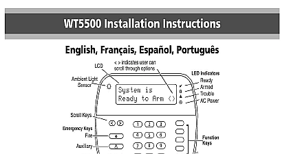
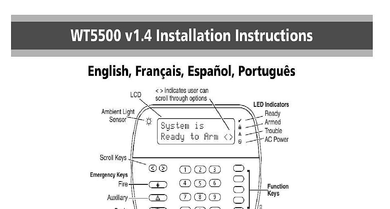
WT5500 v1.4 Installation Instructions Fran Espa Portugu indicates user can through options is to Arm Light Keys Keys Indicators Power Refer to the System Installation Manual for information on limitations regarding product use and function and information on the limitations as to liability of the manufacturer instructions shall be used with the appropriate Control Panel Installation Manual with which this equipment is intended to be used Operating Instructions shall be made available to the user Installation Sheet applies to the following models WT5500 433 WT5500 868 WT5500P 433 WT5500P 868 not dispose the waste battery as unsorted municipal waste Consult your local rules and or laws regarding recycling of this battery it will help protect the environment by reducing the number of bat consumed Some of the materials that are found within the battery could become toxic if not disposed properly and or may affect the environment and indirectly everybody health Instructions WT5500 Wireless Keypad is compatible with the PC9155 and Wireless Panels Temperature range 10 to 55 14 to 131 Humidity MAX 93 R H Plastic enclosure protection degree IP30 IK04 Power adaptor output voltage 4.5VDC 0.5A Models US Latin America SA103A 0506 6U Canada SA103A 0506 6 SA103A 0506G 6 UK SA106C 05BS AUS NZ SA106C 05AS SA106C 05HS Battery 4 AA 1.5 V Energizer Alkaline Low Battery Indication 2.2 V WT5500 current draw 50mA Wall mount tamper 5 programmable function keys Ready Green LED Armed Red LED Trouble Yellow LED AC Green LED Frequency 433.92MHz WT5500 433 WT5500P 433 only Frequency 868.35MHz WT5500 868 WT5500P 868 only DSC recommends that the keypad be powered by the AC adaptor the batteries for EN installations When the power adapter is used batteries provide minimum 24h WT5500 keypad package is available in five distinct configurations Wall Wall Mount w Proximity Desk Stand Accessory Kit and Proximity Only The contents of each are described below contains patented technology for the Proximity Tag WALL MOUNT 1 WT5500 Keypad 1 WT5500BRK Wall Bracket 1 Installation Manual 1 Inner Door Sticker 4 AA Batteries 1 Hardware Pack DESK STAND 1 WT5500 Keypad 1 WT5500DMK Desk Stand 1 WT5500BRK Wall Bracket 1 Installation Manual 1 Inner Door Sticker 1 Power Adaptor 4 AA Batteries 2 Hardware Packs ACCESSORY KIT 1 WT5500DMK Keypad 1 Hardware Pack 1 Power Adaptor WALL MOUNT PROX TAG cid 129 1 WT5500P Keypad 1 WT5500BRK Wall Bracket 1 Installation Manual 1 Inner Door Sticker 4 AA Batteries 1 Hardware Pack 1 PT4 or PT8 Prox Tag 433MHz 868MHz TAGS ONLY 1 PT4 or PT8 Prox Tag 433MHz 868MHz 1 Installation Manual should mount the keypad where it is accessible from designated points entry and exit Once you have selected a dry and secure location perform following steps to mount the keypad Mounting Plate Locate the screw holes 4 at each corner of the mounting plate Use the four screws provided to affix the mounting plate to the wall the mounting tabs are facing you see above diagram Align the four mounting slots in the WT5500 housing with the four tabs protruding from the mounting plate Slide the keypad into place Firmly but carefully snap the keypad down onto the mounting plate To fasten the keypad securely onto the mounting plate locate the two holes in the bottom of the mounting plate then using the two provided in the hardware pack screw the keypad into place Stand WT5500D Insert the four rubber feet found the hardware pack into the provided in the bot of the desk stand Place the desk stand on a secure surface Align the four mounting slots in the WT5500 housing with the four tabs protruding from the desk stand Slide the keypad into place Firmly but carefully snap the keypad down the desk stand To fasten the keypad securely onto the desk stand locate the two holes the top corners of the back of the desk stand Using the two screws screw the keypad to the desk stand Battery Power Slide the keypad up and out from the mounting plate desk stand the screws first if required The bay for the four AA batteries open and visible at the back of the keypad Insert the batteries as directed on the back of the keypad Ensure the polarity is observed Replace the keypad on the mounting plate desk stand Do not mix old batteries with new ones AC Power Slide the keypad up and out from the mounting plate desk stand Locate the power adaptor jack at the back of the keypad housing Place the adaptor plug in the housing indentation perpendicular to the Insert the adaptor plug firmly into the jack Pivot the adaptor plug downwards so that it fits flush with the housing the AC wire along the channel provided in the keypad housing wire will extend through the bottom of the housing Replace the keypad on the mounting plate desk stand in the latter case a channel is provided in the bottom of the desk stand Guide the AC along this channel the wire will extend through an opening in the of the stand Plug the adaptor into a wall outlet Only use the power adaptor 4.5VDC 0.5A 2.25W supplied the kit The socket outlet in which the direct plug in adaptor is must be close to the keypad and easily accessible The plug of adaptor serves as a means of disconnection from the supply mains the Keypad are several programming options available for the keypad see Programming the keypad is similar to programming the rest of the To turn an option on off press the number corresponding to the on the number pad The numbers of the options that are currently on will be displayed along the top of the LCD For information on the rest of your security system please refer to your sys Installation Manual Programming Hold the keys for 2 seconds to enter Language Programming Scroll to the desired language and press cid 2 to select Enter cid 2 8 Installer Code cid 2 Enter 996 cid 2 to reset custom labels to the selected language If Section 075 Option 4 is turned off language programming only be performed while in Installer programming Proximity Tags the prox tags from the system when they are lost or no longer needed Enter cid 2 5 Master Code on the keypad The keypad will display the user number and include the letter if a tag is programmed Enter or select the User Code slot you wish to delete Press cid 2 to delete both the user code and the proximity tag User codes can only be deleted individually User 40 Master Code cannot be deleted a deletion attempt on user code will delete the proximity tag only A user code once deleted must be re enrolled before it can be again the Keypad WT5500 must be configured in tandem with your panel in order for the to function as desired Apply power to the control panel Keypad enrollment is active during the two minutes of system power up Note that the panel Ready and LEDs will be flashing for this two minute period A WT5500 must be turned on during this two minute period for it to be to the panel Simultaneously press and hold cid 2 and 1 by doing so you force the to broadcast its ESN Electronic Serial Number When the keypad has been successfully enrolled on the system this take less than 5 seconds the message Successful be displayed on the keypad LCD for five seconds The Ready and AC will return to their previous state Repeat steps 3 4 on each additional keypad to be enrolled PC9155 only Only one WT5500 can be enrolled with the SCW9055 9057 Brightness Contrast Press cid 2 6 Master Code Use the arrow keys to scroll to Brightness or Contrast Control Press cid 2 to select the setting you want to adjust Brig