DSC WTK5504 - Install Manual - En-Fr-Sp-Po - V1 0 - R002

File Preview
Click below to download for free
Click below to download for free
File Data
| Name | dsc-wtk5504-install-manual-en-fr-sp-po-v1-0-r002-8714963052.pdf |
|---|---|
| Type | |
| Size | 2.48 MB |
| Downloads |
Text Preview
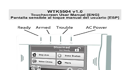
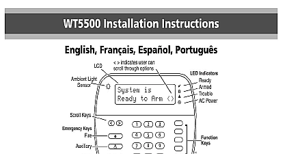
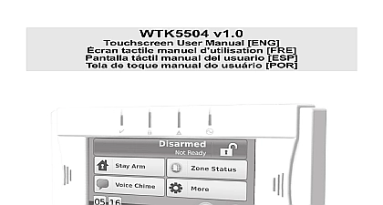
WTK5504 v1.0 Installation Instructions Refer to the System Installation Manual for information on limitations regarding product use and function and information on limitations as to liability of the manufacturer These instructions shall be used with the appropriate Control Panel Installation Manual which this equipment is intended to be used Operating Instructions shall be made available to the user Installation Sheet applies to the following models WTK5504 433 and WTK5504P 433 not dispose the waste battery pack as unsorted municipal waste Consult your local rules and or laws regarding recycling of this battery will help protect the environment Instructions WTK5504 2 Way Wireless Keypad is com with the Alexor PC9155 and Impassa wireless panels The WTK5504 be used with PowerSeries v4.6 and Operating temperature range 0 to 49 32 120 Humidity MAX 93 R H non condensing Power adaptor output voltage 9VDC 0.5A Models US Latin America SA103A 0506 6U SA103A 0506 6 Battery pack NiMH rated 4.8V 2.1Ah Model UL listed DSC P N WTK5504 Input ratings 9VDC 200mA 300mA maximum alarm condi Use only in conjunction with the provided adaptor Wall mount and case tampers Touchscreen display 4.3 WVGA Horizontal viewing angle 130 Vertical viewing angle 70 top 70 bottom Brightness 400cd m2 Voice chime and prompting Ready Armed Trouble and AC status LEDs Proximity tag support WTK5504P only light with adjustable brightness Frequency 433.92MHz When the power adaptor is used the pack provides minimum 24h back up The WTK5504 can be used in UL listed residential fire and burglary instal with all compatible control panels The WTK5504 can be used in UL listed commercial burglary installations Power series models PC1864 PC1832 PC1616 UL ULC commercial burglary instal require the enabling of tamper detec Do not subject the touchscreen to mechanical e g dropping or striking If the touchscreen glass is damaged the liquid fluid inside could leak out Avoid contact the liquid crystal fluid If the liquid crystal comes into contact with your skin or promptly wash it off using soap and run water Seek medical care Do not apply excessive force to the display sur or adjoining areas Excessive force will dis the image on the display Do not use hard or sharp implements to operate touchscreen Operating the touchscreen with implement harder than a finger could the display The WTK5504 must be installed by a Service The WTK5504 contains components that could damaged by static electricity To prevent to the WTK5504 installers and tools be grounded during installation Take extra when working in low humidity conditions The touchscreen is covered by a film to protect display during installation Wear a grounding and remove the protective film slowly to the generation of static electricity that damage the display When installing the WTK5504 avoid locations direct sunlight or close to fluorescent lights WTK5504 keypad package is available in configurations The contents of each pack are described below DESK TAG WTK5504P Keypad WTK5504DMK Stand Installation Manual User Manual NiMH Battery Pack Power Adaptor Hardware Pack PT4 Prox Tag PT4 Manual DESK WTK5504 Keypad WTK5504DMK Stand Installation Manual User Manual NiMH Battery Pack WALL TAG WTK5504P Keypad WTK5504BRK Wall Installation Manual User Manual NiMH Battery Pack Power Adaptor Hardware Pack PT4 Prox Tag PT4 Manual WALL WTK5504 Keypad WTK5504BRK Wall Installation Manual User Manual NiMH Battery Pack Power Adaptor Hardware Pack Power Adaptor Hardware Pack battery pack and additional prox tags are available separately Battery Power a small flat screwdriver into the two on the back of the keypad and release latches see diagram Remove the back cover by opening from the and pivoting open the case the battery pack wire to the battery ter on the keypad Plug the back of the plastic case bottom first and snap both latches in place AC Power the power adaptor jack at the back of keypad housing the adaptor plug in the housing indenta perpendicular to the keypad Insert the plug firmly into the jack the adaptor plug downwards so it fits flush the housing Guide the AC wire along the provided in the keypad housing the will extend through the bottom of the hous for keypad mounting options the adaptor into a wall outlet Use ONLY the power supply supplied this equipment Use of unauthorized supplies may damage the keypad The socket outlet powering the keypad must be near the keypad and easily accessible For UL listed installations secure the adaptor to the AC outlet using the means provided with the adapter This equipment has no mains on switch If the equipment must be quickly from the mains the plug of the plug in power supply is intended to serve the disconnecting device Ensure that access the mains plug and associated socket outlet never obstructed the keypad where it is accessible from points of entry Once a dry and location is selected perform the follow steps to mount the keypad Stand WTK5504DMK Mounting Plate WTK5504BRK the screw holes 4 at each corner of mounting plate the two rubber feet found in the hard pack into the indentations provided in bottom of the desk stand the WTK5504 face down on a secure sur the four mounting tabs protruding from desk stand with the slots in the WTK5504 but carefully snap the desk stand down the keypad desk stand features a channel in the bottom the AC wire along this channel twisting keep the wire flat so it extends through the in the back of the stand Gently pull the to remove any slack fasten the keypad securely onto the desk locate the hole in the bottom centre of the stand Using the screw provided screw the to the desk stand the four screws provided to affix the mount plate to the wall ensure the mounting tabs facing away from the wall the four mounting slots in the WTK5504 with the four mounting tabs protruding the mounting plate the keypad into place but carefully snap the keypad down onto mounting plate fasten the keypad securely onto the mounting locate the screw hole in the bottom of the plate Using the screw provided screw keypad into place order for the WTK5504 to communicate with alarm panel it must be enrolled on the system power to the control panel Keypad is active during the first two min of system power up Note that the panel and AC LEDs onboard LED for will be flashing for this two minute WTK5504 must be turned on during this two period for it to be assigned to the panel the to Enroll button to start the process the keypad has been successfully enrolled the system this should take less than 5 sec the message Successful will displayed on the keypad screen for five sec The Ready and AC LEDs will return to previous state steps 3 4 on each additional keypad be enrolled Enrolling Alexor and Impassa alarm pane