Edwards 100 Series Installation Sheet 2013
File Preview
Click below to download for free
Click below to download for free
File Data
| Name | edwards-100-series-installation-sheet-2013-6301952847.pdf |
|---|---|
| Type | |
| Size | 701.64 KB |
| Downloads |
Text Preview
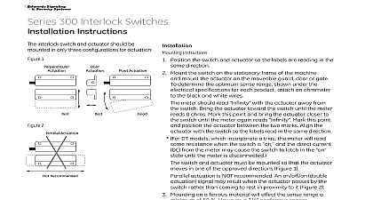
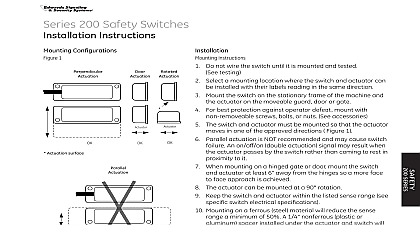
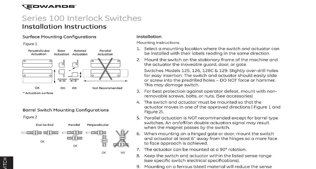
Series 100 Interlock Switches Instructions Mounting Con 1 Actuator Recommended Actuation surface Switch Mounting Con 2 Instructions Select a mounting location where the switch and actuator can be installed with their labels reading in the same direction Mount the switch on the stationary frame of the machine and the actuator the moveable guard door or gate Switches Models 125 126 128C 129 Slightly over drill holes for easy insertion The switch and actuator should easily slide or screw into the predrilled holes DO NOT force or hammer This may damage switch For best protection against operator defeat mount with non removable screws bolts or nuts See accessories The switch and actuator must be mounted so that the actuator moves in one of the approved directions Figure 1 and Figure 2 Parallel actuation is NOT recommended except for barrel type switches An on o double actuation signal may result when the magnet passes by the switch When mounting on a hinged gate or door mount the switch and actuator at least 6 away from the hinges so a more face to face approach is achieved The actuator can be mounted at a 90 rotation Keep the switch and actuator within the listed sense range Mounting on a ferrous steel material will reduce the sense range a minimum of 50 A 1 4 nonferrous plastic or aluminum spacer installed under the actuator and switch will restore most of the lost gap When mounting a metal switch to an ungrounded machine connect the ground lead to one of the switch mounting screws speci switch electrical speci or an RC network is recommended for such loads Particular care must be taken to determine the load of the switch circuit Surges from coils motors contactors solenoids and tungsten must be considered Transient protection such as back to back zener diodes to ensure that maximum ratings of the switch are not exceeded Line capacitance and load capacitance must be considered An in line resistor can be added to limit the inrush current The resistor can only be added in series with the last wire The voltage drop and the power rating of the resistor must be considered Voltage drop I R Watts I2 R I maximum continuous current of the load before the load