Edwards 102 Lens Module Instructions

File Preview
Click below to download for free
Click below to download for free
File Data
| Name | edwards-102-lens-module-instructions-1530928764.pdf |
|---|---|
| Type | |
| Size | 695.56 KB |
| Downloads |
Text Preview
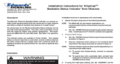
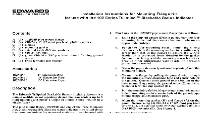
102 Series Triliptical Stackable Beacon Lighting Lens Modules Installation Sheet Operation Edwards Triliptical Stackable Beacon Lighting System is a audible visual signaling device that can contain up to 5 modules and either a single or multiple tone module in a stack components of the Triliptical Stackable Beacon Lighting are UL and cUL listed subassemblies The units assembled are UL and cUL listed for indoor and outdoor The enclosures are NEMA 3R 4X and IP65 optically designed lens modules are available in five blue clear green and red Each lens module a removable cover to allow for easy relamping The module cover features a molded in gasket for weather reliability LED light sources must be used with the matching color and are only available in four colors amber blue and green must be in accordance with local codes To prevent electrical shock do not connect power instructed to do so Assemble the stackable beacon lighting system Figure 1 Pull the captive key in the lens module into the out Place the first lens module on top of the base Push in the captive key to secure the lens module the appropriate light source into board grooves bottom of lens ensuring that the four prongs on the board are aligned with the plug located in the back the lens module When using LED light sources ensure that the color the LED light source and the lens assembly match For further details see the instructions supplied with light source P N 3100701 or the instructions supplied with base P N 3100669 To prevent leakage ensure the magnifier ring on lens cover and the magnifier ring on the lens module are Figure Place the lens module cover on the front of the lens and secure using two captive screws Repeat steps a through e for any remaining modules to 5 Once the last module has been assembled place the on top and secure the cap with the captive screw Apply power to the unit and verify proper operation To prevent electrical shock disconnect power to modules Wait 5 minutes for stored energy in strobe to dissipate before working on unit lens surfaces should be periodically dusted and cleaned a dry soft clean cloth to maintain optimum light visibility If the outside of the lens may be cleaned with water a mild detergent on a well rung out soft clean cloth 2010 UTC Fire Security All rights reserved 2 3100700 REV 2 ISS 06AUG10 1 Assembling the stackable status indicator Cat No shown for illustration purposes only information Signaling Edwards A Division of UTC Fire Security Corporation Inc Town Center Parkway Bradenton FL USA information contact information see www edwardssignaling com 2 3100700 REV 2 ISS 06AUG10 3100700 OFFSET INSTRUCTIONS FOR 102 SERIES STACKABLE STATUS INDICATOR 8 1 2 x 11 SHEET PRINTED BOTH SIDES FOLD TWO TIMES TO SHOWN ON DETAIL WITH PART NUMBER ON THE OUTSIDE STANDARD WHITE OFFSET STOCK TO BE BLACK ON WHITE BACKGROUND MECHANICALS HAVE ALREADY BEEN REDUCED TO ACTUAL SIZE MECHANICALS TO WRITING SIGNALING WOODFORD AVENUE CT 06062 09 C1917 02 3100700 BY DVG