Edwards 105XBRM Installation Sheet

File Preview
Click below to download for free
Click below to download for free
File Data
| Name | edwards-105xbrm-installation-sheet-8742365109.pdf |
|---|---|
| Type | |
| Size | 1.19 MB |
| Downloads |
Text Preview
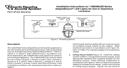
Installation Instructions for Cat 105XBRM Series Location Visual Signals 105XBRM Series visual signals are heavy duty reliable cUL General Utility misc device control unit accessory which when assembled in accordance with instal instructions constitute a UL listed Type 4X enclosure are UL Listed for Marine Use They are designed for use industrial applications or in applications where a Type 4X is required The 105XBRM LED Series are factory in a steady on mode The device can be easily set 65 fpm flashing mode When assembled in accordance these instructions the 105XBRM Series visual signals UL Listed for use in Hazardous Locations with Operating listed in Table 1 specification details see Table 2 Specifications Locations Ratings 31F to 150F 35C to 66C No 24D 120A I I I 1 Hazardous Location Ratings Temperature B C D G 120C 248F 120C 248F 120C 248F prevent electrical shock do not connect until instructed to do so must be in accordance with local codes The lens be positioned up for outdoor applications Select a mounting configuration Figure 5 When Pull field wiring into the mounting attachment 105BX junction box 105BM mounting and 105PM pipe mount attachments non conductive plastic fixtures and not provide earth ground continuity attached to metallic wiring systems they are intended for use with the Series visual signals only when is not required 105BX junction box 105BM mounting and 105PM pipe mount attachments be used with metallic wiring systems when installed at the end of a run the mounting attachment as follows Cat No 105BX Secure the outlet box attachment to mounting surface using two screws not supplied for the surface Attach the adhesive backed to the top of the 105BX mounting box being to line up the holes in the gasket with the holes in the outlet box Cat No 105BM Using the four supplied screws the mounting bracket to Cat No 105BX box attachment as shown in Figure 1 Attach adhesive backed gasket to the top of the 105BM bracket being careful to line up the holes the gasket with the mounting holes in the outlet Cat No 105PM Install 3 4 19 mm conduit the pipe mount attachment onto the 3 4 19 conduit Attach the adhesive backed gasket the top of the 105PM pipe mount attachment careful to line up the holes in the gasket with mounting holes in the outlet box Unscrew the lens from the base The 105XBRM Series Visual Indicator is supplied with a setting of steady on If 65 fpm pattern is desired dipswitch as shown in Figures 2 4 Secure the base to the appropriate mounting attachment four screws supplied Replace the clear gasket the base with the flared open end facing down Attach the unit 18 wire leads to the field wiring as in Figure 3 3101571 ISSUE 3 2010 Phone 800 336 4206 Fax 800 454 2363 Ensuring that the light source is in place screw the lens on the base Apply power and verify operability prevent electrical shock before starting on units disconnect power and wait 5 for stored energy to dissipate lens should be periodically cleaned using a mild deter and water and a soft clean lint free cloth Outlet Attachment Light Source Lens Countersunk screws mount lens to 105BM backed Mounting Screws to mount to 105BX backed Screws to mount to the surface Series Lens Base backed Pipe Mount 19 mm conduit 1 Mounting Cat No 105BM Mounting Bracket 2 Securing the Beacon to the Mounting Series Base Wire Leads units Red Positive units Black Hot units Black Negative units White Neutral nuts supplied Source 3 Wiring the 105XBR Series Beacons 3101571 ISSUE 3 2 Specifications Multi selectable Multi selectable mm mm mm mm mm mm mm mm mm 0.7 mm mm mm Mounting Bracket with 105BX Pipe Mount Attachment Outlet Box Attachment 3 Replacement Parts Lens No White FPM 4 Flash Pattern Dipswitch Settings 3101571 ISSUE 3 Series on a Cat No 105PM Mount Attachment on a Cat No 105BX Box Attachment on a Cat No 105BM Bracket with the No 105BX Outlet Box 5 Mounting Configurations 3101571 ISSUE 3