Edwards 113 Series Installation Instructions

File Preview
Click below to download for free
Click below to download for free
File Data
| Name | edwards-113-series-installation-instructions-7258691034.pdf |
|---|---|
| Type | |
| Size | 1012.21 KB |
| Downloads |
Text Preview
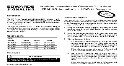
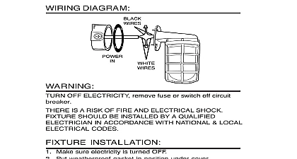
Installation Instructions for MachlightTM Status Indicator Edwards MachlightTM Machine Status Indicator is a multi that contains three light modules red amber and green in single tower unit is UL and cUL listed for Industrial Control indoor appli UL 508 unit optically designed lenses are vertically fluted and eas removed in order to facilitate relamping or to resequence the colors unit is available in either a surface or pole mount version in or 120VAC Each version is available as a steady or model All models have flying leads for connecting field See Table 1 for specifications and Table 2 for product Compatibility electrical input characteristics for PLC compatible signals are in Table 3 Signals with these characteristics may be di connected to PLC output cards that do not exceed these characteristics To mount the unit to the top of a machine drill a 1 2 hole in the mouting surface Remove the bottom nut washer and mounting bracket and feed the wiring through the mounting hole Fasten the pole the surface using the removed mounting nut and washer Using wiring nuts connect field wiring to the unit as follows Connect the black lead marked with the red tag to the field wire positive DC or AC hot lead Connect the black lead marked with the orange tag to the field wire positive DC or AC hot lead Connect the black lead marked with the green tag to the field wire positive DC or AC hot lead Connect the white lead to the field negative DC or AC lead field ground Connect the unit green with yellow stripe ground lead Apply power to the unit and verify proper operation must be in accordance with the latest edition of the Electrical Code and other governing standards and codes standard installation prevent electrical shock disconnect power to the For direct surface mount versions perform the following Replacement Using Figure 1 as a guide mark the three mounting holes the center wiring clearance hole on the mounting Drill the three mounting holes and the the wiring clearance in the mounting surface prevent electrical shock do not connect power instructed to do so Loosen the screw on the units top cap and remove the top cap Remove the lens assemblies until the affected bulb is reached Remove the bulb by pushing down slightly and turning Replace the bulb Reassemble the removed lens assemblies in desired order Note orientation of the top cap upon reassembly Ensure recessed are positioned to provide clearance from top posts Reattach the top cap by securing the top cap screw prevent abrasion of wiring insulation ensure wire clearance hole is adequately protected lens surfaces should be periodically dusted and cleaned with dry soft clean cloth to maintain optimum light visibility If nec the outside of the lens may be cleaned with water and a mild on a well rung out soft clean cloth the unit wiring through the wiring clearance hole using the screws and nuts supplied attach the unit the mounting surface For pole mount versions perform the following To mount the unit to the side of a machine remove the mounting nut washer and mounting bracket Use mounting bracket as a guide to drill two holes in the surface Secure the mounting bracket to the using appropriate hardware not supplied the signal to the mounting bracket using the mounting nut and washer CT 203 699 3300 FAX 203 699 3365 CUST SERV 203 699 3078 TECH SERV 3100543 ISSUE 1 2003 1 Specifications Ratings AC 50 60 Hz 24V DC 0.24A AC 50 60 Hz 0.062A AC 50 60 Hz 24V DC 0.24A AC 50 60 Hz 0.062A AC 50 60 Hz 24V DC 0.24A AC 50 60 Hz 0.062A AC 50 60 Hz 24V DC 0.24A AC 50 60 Hz 0.062A Watts Watts Watts Watts Watts Watts Watts Watts 2 Descriptions Trade 301 Trade 301 Trade 301 Trade 301 Life Hours Hours Hours Hours Hours Hours Hours Hours Light Sources Pole Mount 24V AC DC Red Green and Amber Lenses Light Sources Pole Mount 120V AC Red Green and Amber Lenses Light Sources Pole Mount 24 AC DC Red Green and Amber Lenses Light Sources Pole Mount 120v AC Red Green and Amber Lenses Light Sources Surface Mount 24V AC DC Red Green and Amber Lenses Light Sources Surface Mount 120V AC Red Green and Amber Lenses Light Sources Surface Mount 24 AC DC Red Green and Amber Lenses Light Sources Surface Mount 120 AC Red Green and Amber Lenses No No AC DC AC AC DC AC AC DC AC DC AC No AC volts at 50 60 Hz 3 PLC Compatibility off state current mA on mA inrush duration 5 5 5 5 5 5 5 5 3100543 ISSUE 1 1 Surface Mount Template