Edwards 116DEXMST-FJ Installation Instructions
File Preview
Click below to download for free
Click below to download for free
File Data
| Name | edwards-116dexmst-fj-installation-instructions-5487302619.pdf |
|---|---|
| Type | |
| Size | 687.57 KB |
| Downloads |
Text Preview
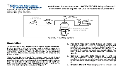
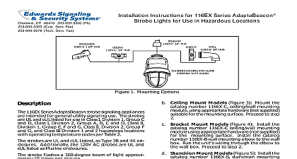
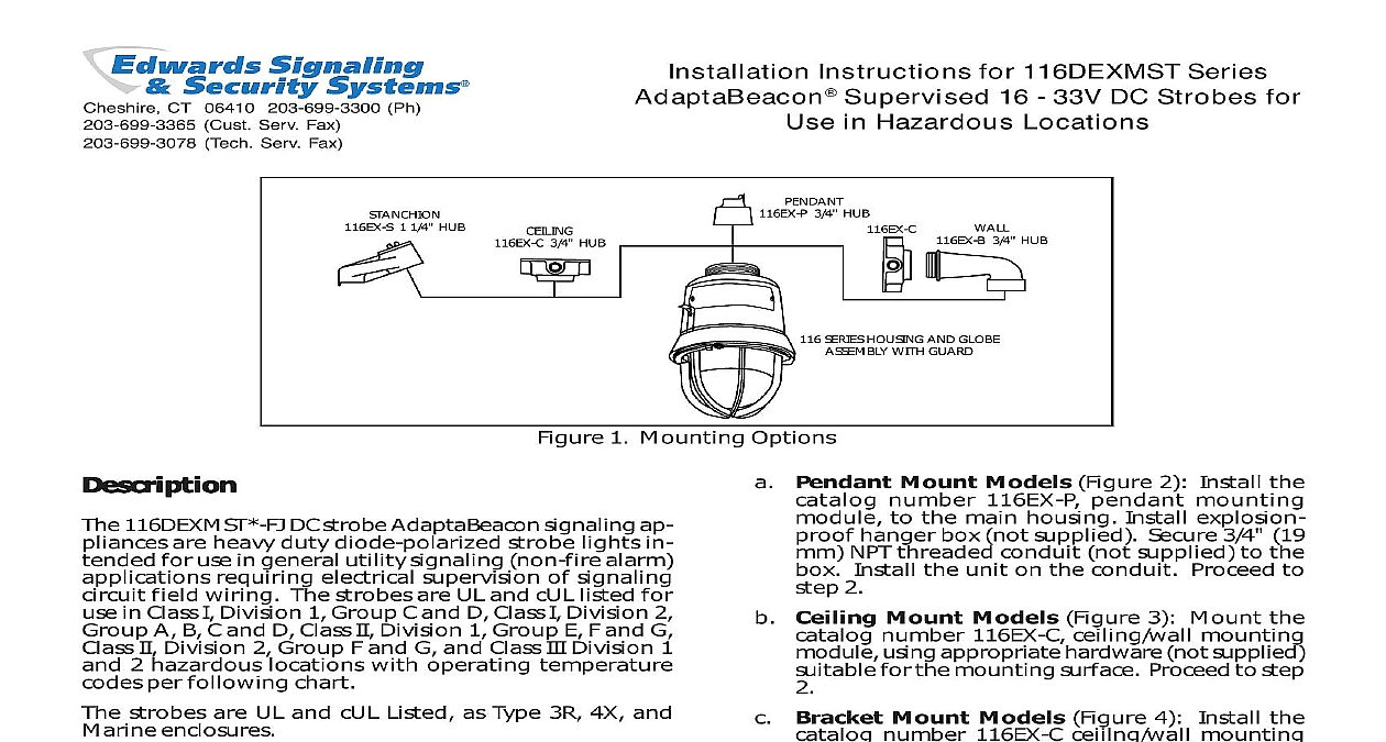
Cheshire CT 06410 203 699 3300 Ph Cust Serv Fax Tech Serv Fax Instructions for 116DEXMST Series Supervised 16 33V DC Strobes for in Hazardous Locations 1 1 4 HUB 3 4 HUB 3 4 HUB 3 4 HUB SERIES HOUSING AND GLOBE WITH GUARD 1 Mounting Options 116DEXMST FJ DC strobe AdaptaBeacon signaling ap are heavy duty diode polarized strobe lights in for use in general utility signaling non fire alarm requiring electrical supervision of signaling field wiring The strobes are UL and cUL listed for in Class I Division 1 Group C and D Class I Division 2 A B C and D Class II Division 1 Group E F and G II Division 2 Group F and G and Class III Division 1 2 hazardous locations with operating temperature per following chart strobes are UL and cUL Listed as Type 3R 4X and enclosures strobe flashes a 360 degree beam of light approxi 65 times per minute strobes are available in pendant bracket ceiling or mount models Figure 1 reduce the risks of ignition of hazardous atmo and shock do not apply power to the unit installation has been completed and unit is assembled and secured this unit in accordance with the applicable require in the latest edition of the National Electrical Code Canadian Electrical Code Mount using the following applicable method Pendant Mount Models Figure 2 Install the number 116EX P pendant mounting to the main housing Install explosion hanger box not supplied Secure 3 4 19 NPT threaded conduit not supplied to the Install the unit on the conduit Proceed to 2 Ceiling Mount Models Figure 3 Mount the number 116EX C ceiling wall mounting using appropriate hardware not supplied for the mounting surface Proceed to step Bracket Mount Models Figure 4 Install the number 116EX C ceiilng wall mounting using appropriate hardware not supplied the mounting surface Install the catalog 116EX B wall mounting elbow to the wall Run the unit wiring through the elbow to wall box Proceed to step 2 Stanchion Mount Models Figure 5 Install the number 116EX S stanchion mounting to the main housing Run the unit wires the 1 1 4 conduit to the appropriate box Install the unit on the conduit to step 2 Connect field earth ground wire to ground screw or ground via conduit system Wire the unit in accordance with Figure 6 See Table for required supply wire temperature ratings As appropriate install the fixture on the mounting reduce the risk of ignition of hazardous atmo and shock keep assembly tightly closed circuits are energized Apply power to the unit and ensure proper function 3100758 ISSUE 1 2004 3 4 3 4 1 4 9 16 7 16 1 16 13 16 2 Detail of Pendant Mounting 3 Detail of Ceiling Mounting 1 4 3 4 3 4 1 2 3 4 1 4 1 4 1 4 4 Detail of Wall Bracket Mounting 5 Detail of Stanchion Mounting DC polarity of circuit shown in supervisory state signal inactive Circuit polarity to reverse to activate signal Electrical supervision requires wire run to be broken at each device Device for constant input voltage Do not connect to or pulsating voltage Power Source Signaling Device symbol nut symbol Resistor required with system For use without field wire supervision installer can tie the two white leads together and tie the two leads together 6 Wiring Diagram 3100758 ISSUE 1 the unit as follows Figure 7 reduce the risk of ignition of hazardous atmo and shock keep assembly tightly closed circuits are energized reduce the risk of ignition of hazardous atmo and shock disconnect from the supply and and allow five 5 minutes for stored energy to before disassembling the unit Loosen the 3 guard screws and remove the guard Loosen the globe and ring assembly set screw Insert suitable tool into the notches in the globe and ring and loosen the assembly by prying in a direction Remove the ring and assembly Refer to Table 1 for the correct replacement catalog and replace the necessary part To replace simply screw the unit on until it seats firmly its gasket Tighten the unit another 1 8 to 1 4 Tighten the setscrew Reinstall the guard where applicable and secure using three supplied screws After the unit is assembled apply power and make the unit functions properly Tube Ring 7 Disassembly of the 116EX Series AdaptaBeacons 3100758 ISSUE 1 1 116 Series AdaptaBeacons 33V DC 0.55A NPT NPT 1 4 NPT fpm Tube Less Module Module Module Module Bracket Elbow in this position denotes color of the globe A amber B blue C clear G green R red or magenta 2 Ratings Wire Marking I Div 2 A B 215 230 Temperature I Div 1 2 II III Div 1 II III Div 2 C D E F G 85 85 120 135 F G 120 135 Edwards 699 3300 3100758 ISSUE 1