Edwards 1500-7 and 1500-12 Installation Instructions

File Preview
Click below to download for free
Click below to download for free
File Data
| Name | edwards-1500-7-and-1500-12-installation-instructions-4736082915.pdf |
|---|---|
| Type | |
| Size | 618.52 KB |
| Downloads |
Text Preview
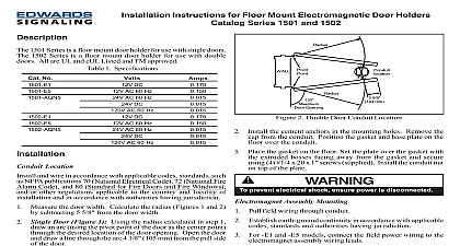
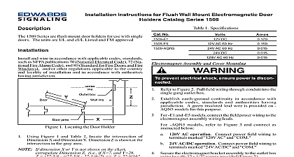
Installation Instructions for 1500 Series Holder Extension Kits the extension rod into the armature base and secure 10 32 x 1 1 2 38 mm armature securing screw 1 3 spherical bushings supplied and flat washers with 1500 7 and 1500 12 only into the rod assembly as shown in Figure 2 or Figure 3 applicable Secure catch plate in extension rod using x 1 25 mm securing screw Figure 2 adjustable units only adjust the extension length by the knurled locking nut extending the rod to desired length and retightening the knurled locking Figure 2 Proper alignment of the catch plate and the helps ensure sufficient holding force Align the catch plate with the electromagnet by moving extension arm up or down and back or forth while adjusting the catch plate against the There should be no gap between the catch plate the magnet After the desired extension length and contact alignment been achieved perform the following Figure 2 Using a 5 32 4 mm Allen Wrench supplied lock extension arm into position by tightening the securing screw Figure 2 Do not Perform an operational check of the Electromagnetic Holder as outlined in the installation instruction with the door holder For more detailed information on installation of the door see the instructions supplied with the door holder CT 06410 203 699 3300 Ph Cust Serv Fax Tech Serv Fax Edwards 1500 Series Door Holder Extension Kits are used it is desired to hold doors open and where a standoff dis between the magnet assembly and the armature base is re The extension rod kit can be used with Edwards 1504 1508 and 1509 Series Door Holders Parts from these door are used with the extension kits to form a complete unit Number Range 1 2 38 mm Fixed 51 mm Fixed 8.00 162 203 mm 12 213 305 mm extension kits project a significant distance from doors they are mounted on and should therefore mounted as high as possible to preclude interfer or personal injury the extension kit as follows Remove the 10 32 x 1 1 2 38 mm armature securing and remove the catch plate from the armature base 1 spherical bushings removed in Step 1 a as shown Figure 2 or Figure 3 as applicable If bushings are replace with bushings supplied with the door extension kit 1 Armature Base Assembly 3100331 ISSUE 2 2004 x 1 1 2 38 mm Securing Screw with door holder Base supplied with door holder Spherical Bushings Tube Locking Nut UNF x 1 25 mm supplied Spherical Bushings Flat Washers UNF Nut Plate with door holder 2 Extension Rod Assembly Adjustable 1500 7 and 1500 12 Model UNF x 1 25 mm supplied Plate with door holder Spherical Bushings UNF Nut Spherical Bushings Base with door holder x 1 1 2 38 mm Securing Screw with door holder 3100331 ISSUE 2 3 Extension Rod Assembly Adjustable 1500 1 and 1500 2 Model