Edwards 439D FA Bell Installation Instructions

File Preview
Click below to download for free
Click below to download for free
File Data
| Name | edwards-439d-fa-bell-installation-instructions-1247563890.pdf |
|---|---|
| Type | |
| Size | 685.64 KB |
| Downloads |
Text Preview
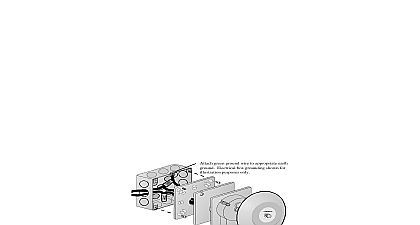
Installation Instructions for Catalog Series 439D Alarm Bell cid 12 cid 10 cid 13 cid 11 cid 14 cid 7 cid 2 cid 5 cid 12 cid 8 cid 6 cid 9 cid 10 Edwards 439D series models are heavy duty dc pow vibrating fire bells They are designed for public signaling in accordance with the latest edition of 72 These vibrating bells produce a long continu ringing sound See table below for electrical specifi DC not apply power to bell until installation has been to starting installation refer to Figure 1 for bell size metal mounting plate supplied with these bells mounts on the surface of any single or double gang 3 box 4 octagon box or 4 square wall box or plaster cover boxes and covers supplied by others outdoor mounting use Cat No 449 weatherproof box separately as shown in Figure 1 Box Mounting Figure 3 Remove screw and lockwasher from front of gong and gong Retain hardware and gong Pull bell lead wires through hole in insulator 2 Feed the power source wiring from electrical outlet through the metal mounting plate Ensure that mounting plate is aligned with the word TOP at top and facing out and secure metal mounting to electrical outlet box with appropriate not supplied Align the tabs on the back of the gong with the grooves the bell body and secure with the screw and removed in step 1 Mounting Figure 4 Remove screw and lockwasher from front of gong and gong Retain hardware and gong Cut bell wire leads as needed and strip wire leads back Ensure that the mounting plate is aligned with the TOP at the top and facing out and secure metal plate to surface using screws appropriate the mounting surface not supplied Place over studs on mounting plate Figure 2 wire run to provide electrical supervision Do NOT bell lead wires around signal circuit wiring See Figure 4 Using wire nuts not supplied connect to circuit Push connected wires into bell through hole in bell body base while mounting and bell body onto studs of metal mounting Secure the bell body onto the metal mounting using two lockwashers and two nuts supplied Align the tabs on the back of the gong with the grooves the bell body and secure with the screw and removed in step 1 Power device will not operate without electrical power As frequently cause power interruptions we suggest you further safeguards with your local fire protection Apply power to fire alarm or system control panel an alarm to activate bell and verify that it Reset panel to silence bell and return panel to mode wire run to provide electrical supervision Do NOT bell lead wires around signal circuit wiring Using wire nuts not supplied connect wires to circuit push wires and connections down inside the box Figures 3 and 5 Mount insulator and bell body onto studs of metal plate Figures 2 and 3 Secure using two and two nuts supplied disconnect all power before servicing or cleaning bell annually for accumulation of dirt and clean necessary CT 203 699 3300 FAX 203 699 3365 CUST SERV 203 699 3078 TECH SERV P 047550 0590 ISSUE 6 2001 Gong Gong Gong bell base to mounting with 2 lockwashers and nuts supplied with bell 3 4 19 mm mm box No 449 3 4 19 mm 1 16 mm 1 2 mm 5 8 mm mm mm mm line base 5 8 mm Leads black and 2 red stripped 29 32 mm 11 32 mm 15 32 mm 1 Bell Dimensions wall box mounting bell wire exit hole in mounting for bringing bell lead wires out connections in electrical outlet box surface mounting wire entrance hole in bell body for wiring to bell lead connections connections in bell housing insulator View View Studs 2 Metal Mounting Plate and Insulator green ground wire to appropriate earth Electrical box grounding shown for purpose only Plate Body for gong Plate Body for gong 3 Installing the Adaptabel Wall Mount 4 Installing the Adaptabel Surface Mount for 4 wire bells to existing 3 wire signal circuit for 4 wire bells of line supervised circuit or appliance of line supervised circuit or appliance Use leads for connections as shown Wire run MUST be broken to provide supervision of signal P 047550 0590 ISSUE 6 2 5 Wiring Diagrams