Edwards 48XBRM Series Instructions

File Preview
Click below to download for free
Click below to download for free
File Data
| Name | edwards-48xbrm-series-instructions-1450679238.pdf |
|---|---|
| Type | |
| Size | 1.01 MB |
| Downloads |
Text Preview
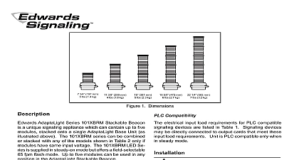
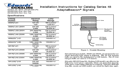
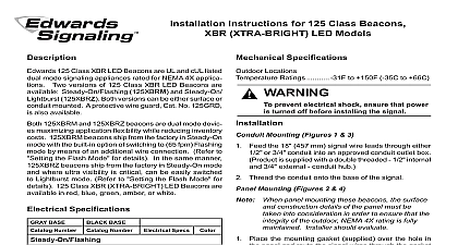
Installation Instructions for 48XBRM Series XTRA BRITETM LED DUAL MODE Visual Catalog Series 48XBRM Visual Indicator is a UL and cUL signaling appliance rated for NEMA 4X applications signals are suitable for indoor or outdoor weatherproof and are available in AC and DC models as listed 48XBRM Series XBR XTRA BRITETM LED Dual Mode are well suited in high ambient noise level areas where ear protection must be worn These LED are also ideal for high vibration applications and where long lamp life is advantageous 48XBRM LED ship from the factory in steady on mode and can readily transformed by changing the dipswitch setting to FPM flashing mode 48XBRM series signals can be mounted on 1 2 13mm conduit indoor or outdoor or direct surface mounted only For outdoor weatherproof installation the must be mounted with their lens dome facing directly When installing indoors these signals can be mounted any position Specs DC 0.215A AC 0.108A DC 0.215A AC 0.108A DC 0.215A AC 0.108A DC 0.215A AC 0.108A DC 0.215A AC 0.108A Specifications Number AC 50 60 Hz Specifications Locations Ratings 31F to 150F 35C to 66C Compatibility devices may be directly connected to PLC output that meet the electrical input load specifications listed Table 1 When signaling device flash rates are to be con via PLC dip switch settings should be left in steady mode as originally shipped from the factory prevent electrical shock ensure that power disconnected before installing the signals in accordance with the latest edition of the National Code and local regulations Install the signals one of the following applicable mounting procedures Mounting Indoor or Outdoor Figure 1 prevent leakage and a potential shock when mounting outdoors the signal be installed with the lens or dome facing up a small flat blade screwdriver between the locking and the lens Gently push down and then up unseating the lens Pull the lens up and off of signal mounting base being careful not to damage internal circuit Setting the Flash Pattern The 48XBRM Series Visual is a dual mode device supplied with a default of steady on If flashing 65 fpm mode is desired dipswitch as shown in Figure 4 Refer to Figure 3 for location After setting the flash pattern carefully place the lens on the unit and snap in place Route the signal wire leads through 1 2 NPT conduit supplied and thread the conduit into the signal base Connect the field wiring to the signal wire leads as in the Wiring Section Phone 800 336 4206 Fax 800 454 2363 3101569 ISSUE 3 2010 Surface Mounting Indoor Only Figure 2 The installer should use suitable hardware for the installation a small flat blade screwdriver between the locking and the lens Gently push down and then up unseating the lens Pull the lens up and off of signal mounting base being careful not to damage internal circuit Setting the Flash Pattern The 48XBRM Series Visual is supplied with a default setting of steady on flashing 65 fpm is desired set dipswitch as shown in 4 Remove the two knockouts for mounting screws from signal base Place the 3 3 4 95mm mounting provided in the direct surface mounting kit on mounting surface and mark the center of the three in the gasket on the mounting surface Remove gasket and drill a 3 8 10mm hole at each of the positions the two rubber expansion plugs provided in the kit into the two outer holes in the mounting Route the wire leads from the signal base through the hole in both the mounting gasket and surface The should be run through an approved raceway or connected between the bottom of the signal base an approved junction box not supplied Bring wire into the junction box Refer to the signal label for rating Align the outer holes in the mounting gasket with the in the surface Insert two screws with lockwashers the two outer holes in the signal base and align screws with the rubber expansion plugs as shown Figure 2 Press the signal base firmly against the surface and tighten the screws Carefully place the lens back on the unit and snap in Connect the field wiring to the signal wire leads as in the Wiring Section For AC models use wire nuts not supplied and connect signal black and white wire leads to the power wires Polarity is not important For DC models connect the signal red wire to the power source wire and connect the signal black to the negative power source using appropriate not supplied Polarity must be observed source view of base of two for surface 1 Conduit Mounting and support plate Wire Leads 13 mm NPT supplied units Red Positive units Black Hot units Black Negative units White Neutral Mounting supplied DC models Lockwashers with models base support plate gasket with models Rubber expansion supplied with models surface in field Enclose wiring within an approved interconnecting the appliance junction box in accordance with codes standards and 2 Direct Surface Mounting of the Series Signals 3101569 ISSUE 3 prevent damage to the lens do not use materials or cleaners clean the lens surface with a soft cloth or sponge water or a mild detergent solution to maintain optimum visibility Ensure that the lens is completely dry before the signal Light Pattern 3 Dipswitch Location FPM 4 Flash Pattern Dipswitch Settings 1 PLC Compatibility No 24D 120A AC volts at 50 60 Hz DC AC off state current mA on mA inrush duration Parts 48XBRM Series color of lens by adding one of the following letters to the catalog number A amber G green or R red C clear used with white LEDs Example A red lens for the 48XBR signal is 96 LR Number 3101569 ISSUE 3 800 336 4206 800 454 2363 519 376 2430 519 376 7258 852 2907 8108 852 2142 5063 61 3 9239 1200 61 3 9239 1299 32 2 725 11 20 32 2 721 86 13 America 305 593 4301 305 593 4300