Edwards 53 Series Installation Instructions

File Preview
Click below to download for free
Click below to download for free
File Data
| Name | edwards-53-series-installation-instructions-5739824160.pdf |
|---|---|
| Type | |
| Size | 604.50 KB |
| Downloads |
Text Preview
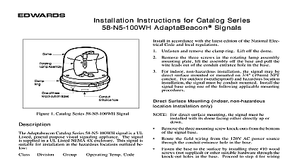
Installation and Maintenance Instructions for Series 53 AdaptaBeacon Signals catalog series 53 Adaptabeacon signals are dc operated lights The signals may either be conduit mounted or surface mounted and are suitable for indoor or outdoor installation A hardware kit is included with signals for direct mounting applications DC DC DC DC letter in this position of the catalog number the color of the supplied dome A amber blue C clear G green M magenta or R red Surface Mounting Remove the two knock outs for the mounting screws the bottom of the base See Figure 1 for the of knock outs Place the gasket provided in the hardware kit on the surface and mark the center of the three holes the gasket on the surface Remove the gasket and a 3 8 9.5 mm hole at each of the marked the two rubber expansion plugs provided in the kit into the two outer holes in the mounting as indicated in Figure 2 Route the wiring from the required power source for signal refer to the signal label for the voltage through the center holes in the mounting gasket and base Align the holes in the gasket with the holes in the base the two screws with lockwashers provided in hardware kit through the mounting holes inside base and align the screws with the rubber expansion as shown in Figure 2 Press the base firmly the mounting surface Using wire nuts not supplied connect the signal red lead to the positive power source lead and connect white wire lead to the negative power source wire the connected wires inside of the base and reassemble signal on the base that power is disconnected before installing the See Figure 1 Remove the screw in the clamp ring remove ring and lift off the dome the base using one of the following applicable disconnect power before disassembling the Replacement installing indoors the signal may be mounted the dome facing either directly up or down For installation the signal must be installed with dome facing directly up Mounting Route the wiring from the required power source for signal refer to the signal label for voltage rating a 1 2 13 mm NPT conduit not supplied through the conduit entrance hole in the base the base on the conduit to the Replacement Parts for the required lamp Dis the power remove the screw in the clamp ring remove ring and lift the dome off the signal Replace the lamp materials or cleaners must not be used to the dome signal dome should be periodically cleaned to maintain light visibility The dome may be cleaned with a soft or sponge using a mild detergent Dry the dome thor before replacing is a registered trademark of the Edwards Company CT 203 699 3000 FAX 203 699 3075 ISSUE 4 1997 1 Catalog Series 53 Rotating Light 2 Direct Surface Mounting of Signal replacement parts listed below for the 53 series signals are available from your local Edwards distributor Number Lamp Dome Parts color of the replacement dome by adding the letter A B C G M or R to the catalog number for example a red for the 53 E1 series signal is 52 LR ISSUE 4