Edwards 5530M-485 Installation Instructions

File Preview
Click below to download for free
Click below to download for free
File Data
| Name | edwards-5530m-485-installation-instructions-1876950243.pdf |
|---|---|
| Type | |
| Size | 1.20 MB |
| Downloads |
Text Preview
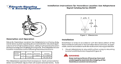
Installation Instructions for Catalog Series 5530M 485 Millennium Signal 7 8 mm 1 4 mm mm 1 2 mm 3 4 mm 1 4 mm 1 Dimensions and Operation and Operation and Operation and Operation and Operation Adaptatone is a heavy duty tone selectable stand indoor outdoor audible signaling device intended industrial applications where high audible output and reliability are required The Adaptatone series are UL and cUL Listed as Audible Signal for use in the following hazardous locations I Div 2 Groups A B C D II Div 2 Groups F G III Div 1 and 2 135C 100C Adaptatone operates from local power and sounds a decibel signal determined by the setting of minia programming switches inside the unit The may be programmed for any of the 27 tones in Figure 7 direction and the output level are easily adjust Specifications Specifications Specifications Specifications Specifications 9 Pounds 4.1 kg Locations UL Standard UL1604 Temp 41F to 104F 5C to 40C Locations Ambient Temp 40F to 151F 40C to 66C Specifications Specifications Specifications Specifications Specifications Volume On A DC DC AC 50 60 Hz AC 50 60 Hz DC DC AC 50 60 Hz AC 50 60 Hz DC DC AC 50 60 Hz AC 50 60 Hz Adaptatone may be mounted to any flat surface or be used as a freestanding unit mounted to a rigid The Adaptatone must be installed in accordance the latest edition of the National Electrical Code or regulations applicable to the country and locality installation and by a trained and qualified electrician installation care must be taken so that components the printed circuit board are not damaged Mount Adaptatone as shown in Figure 2 Flat Surface Mounting Secure unit to surface using the 4 mounting holes in mounting plate on the rear of the box Use 10 x 3 76 mm wood screws furnished loose other hardware not supplied suitable for the surface Rigid Pipe Mounting Loosen the 4 cover screws the signal box and lift off signal box cover CT 203 699 3300 FAX 203 699 3365 CUST SERV 203 699 3078 TECH SERV 3100345 ISSUE 2 2002 Cover screws are captive Do not remove from the center knockout in lower wall of box mount box to a 1 2 12.7 mm conduit pipe suitable connector wires through a knockout hole in the bottom the box from a raceway that is with its connections the 1 2 12.7 mm conduit knockout hole approved the same degree of protection and enclosure type by the application Use the provided plastic on the barrier to the electronics to separate power leads from signal and tone initiating per NEC Figure 5 prevent fire and shock wire the Adaptatone only as in this installation instruction Wire as follows referring to Figures 5 and 6 Connect green and yellow striped earth ground to earth ground Connect the RS485 wires to terminals TX RX and on the RS485 COMM board Figure 6 using the optional MR201 C relay connect the to RELAY and RELAY on the RS485 COMM Figure 6 Connect incoming power to wire leads using a splice or other method listed certified or approved by local authorities Leads black and white star nut to speaker Box Cover Collar and connections supplied to 12.7 mm knockout 10 x 3 76 mm or other hardware for the mounting surface 2 Adaptatone Mounting Optional Connect external 24V DC battery not in series with separate diode assembly 2600010 supplied to TB1 terminals 3 and 4 the main board as shown in Figures 3 and 4 marked on the diode assembly Terminal Block TB1 can be unplugged from the board to complete wiring as shown in 3 VOLTAGE is present when product is energized High may cause harm to personnel in close proximity Adjust volume level if desired by turning located on the main board Figure 11 ensure integrity of the enclosure Ensure the cover part number P 007549 0069 is adhered into at cover perimeter before replacing the signal box that the 4 collar gaskets part number P 041930 are in place on each cover screw before securing the box cover securing cover start screws by hand making sure are threaded into tapped holes in housing bosses securing with a screwdriver Torque signal box cover to a minimum of 20 in lbs This ensures the tight fit Tightly secure the signal box cover using 4 retained Torque signal box cover screws to a minimum of 20 screws ensure integrity of the Adaptatone assembly when the speaker direction make sure threads in the remain fully engaged and do not turn speaker than 360 degrees from the original factory installed To adjust speaker direction loosen large star nut 2 and turn speaker to the approximate desired ensure integrity of the Adaptatone assembly prior to of installation make sure threads in the are fully engaged and ensure that the star nut is tight Regardless of speaker direction adjustment it is that the star nut be tightened wrench tight ensure the speaker position is maintained securely Verify operability For tone selection and operation refer to Figure 7 the Protocol section of these installation 3100345 ISSUE 2 2 Adaptatone should be tested annually or as required the authority having jurisdiction to ensure continuous and TTTTTestestestestest and and and and that power is disconnected before cleaning inside of the unit semi annually for accumulation of dirt if necessary Setting Unit Address and Network Baud Rate the 8 position dip switch S1 on the top edge of the RS485 COMM board Figure 6 Unit address range is 00 1F hex 00 31 decimal Refer to Table 2.2 for unit address configuration Set S1 1 5 for the desired unit address configuration 2.2 Unit Address Switch Configuration Address 3 3100345 ISSUE 2 COMM supports 1200 2400 9600 and 19200 baud rate using 8 data bits and one