Edwards 5530M & 5530MHV
File Preview
Click below to download for free
Click below to download for free
File Data
| Name | edwards-5530m-5530mhv-9352067481.pdf |
|---|---|
| Type | |
| Size | 946.54 KB |
| Downloads |
Text Preview
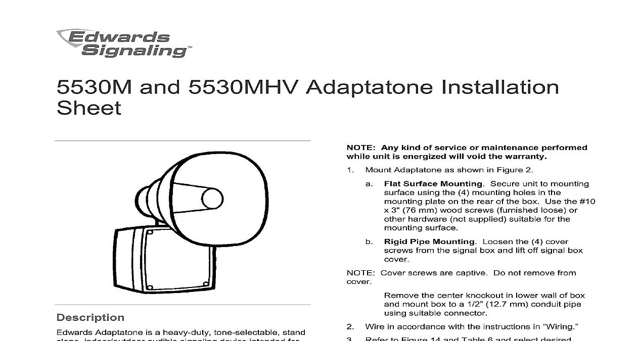
and 5530MHV Adaptatone Installation Any kind of service or maintenance performed unit is energized will void the warranty Mount Adaptatone as shown in Figure 2 Flat Surface Mounting Secure unit to mounting using the 4 mounting holes in the plate on the rear of the box Use the 10 3 76 mm wood screws furnished loose or hardware not supplied suitable for the surface Rigid Pipe Mounting Loosen the 4 cover from the signal box and lift off signal box Cover screws are captive Do not remove from the center knockout in lower wall of box mount box to a 1 2 12.7 mm conduit pipe suitable connector Wire in accordance with the instructions in Refer to Figure 14 and Table 6 and select desired Set miniature programming switches on the input HIGH VOLTAGE is present when product is High volume may cause harm to personnel in proximity Adjust volume level if desired by turning potentiometer on the main board Figure 14 To ensure integrity of the enclosure Ensure cover gasket part number P 007549 0069 is adhered groove at cover perimeter before replacing the signal cover that the 4 collar gaskets part number P 041930 are in place on each cover screw before securing the box cover securing cover start screws by hand making sure are threaded into tapped holes in housing bosses securing with a screwdriver Torque signal box cover to a minimum of 20 in lbs This ensures the required fit Tightly secure the signal box cover using 4 retained screws Adaptatone is a heavy duty tone selectable stand indoor outdoor audible signaling device intended for applications where high audible output and reliability are required Additionally the Millennium series are UL and cUL Listed as Signal Appliances for use in the following hazardous Adaptatone operates from local power and sounds a decibel signal determined by the setting of miniature switches inside the unit The Adaptatone may programmed for any of the 55 tones listed in Table 6 direction and the output level are easily adjustable Adaptatone may be mounted to any flat surface or may used as a freestanding unit mounted to a rigid pipe The must be installed in accordance with the latest of the National Electrical Code or other regulations to the country and locality of installation and by a and qualified electrician catalog numbers ending in AQ 24 VAC power must be isolated from mains or line power To prevent fire shock and component damage work including circuit board removal should be while the circuit is energized 2010 UTC Fire Security All rights reserved 7 3100006 REV 4 ISS 09AUG10 Adaptatone should be tested annually or as required by authority having jurisdiction to ensure continuous 1 Adaptatone mounting Torque signal box cover screws to a minimum of 20 in To ensure integrity of the Adaptatone assembly adjusting the speaker direction make sure threads in enclosure remain fully engaged and do not turn speaker than 360 degrees from the original factory installed To adjust speaker direction loosen large star nut 1 and turn speaker to the approximate desired Regardless of speaker direction adjustment it is that the star nut be tightened wrench tight to the speaker position is maintained securely Verify operability wires through a knockout hole in the bottom of box from a raceway that is with its connections to 1 2 12.7 mm conduit knockout hole approved for same degree of protection and enclosure type by the application Use the provided plastic tie on the barrier to the electronics to separate power leads from signal and tone initiating per NEC Figure 4 Wire as follows referring to Figure 4 Connect green and yellow striped earth ground to earth ground Select the appropriate method for wiring to the input from Figure 5 through Figure 13 Connect incoming power to wire leads using a butt or other method listed certified or otherwise by local authorities Leads are both black AQ and N5 models and are black and white for models Optional Connect external 24V DC battery not in series with separate diode assembly 2600010 supplied to TB1 terminals 3 and 4 the main board as shown in Figure 2 and 3 and marked on the diode assembly Terminal Block TB1 can be unplugged from the board to complete wiring as shown in Figure 2 and testing To prevent fire shock and component damage work including circuit board removal should be while the circuit is energized Any kind of service or maintenance performed unit is energized will void the warranty the unit semi annually for accumulation of dirt if necessary To prevent fire and shock wire the Adaptatone as described in this installation instruction 2 Terminal block TB1 3 Wiring to terminal block TB1 input circuit 7 3100006 REV 4 ISS 09AUG10 4 Wiring the Adaptatone 7 24 VDC strapped input 24 V input board 8 Wiring to 24 V input board with an open collector 5 Wiring a dry relay contact to 24 V input board 1 refer to Applications Engineering for compatibility earlier versions of Adaptatone 9 Connecting 24 V input board in parallel with limit of 5 models 6 Wiring a dry relay contact to 24V input board method 10 Connecting 24 V input board to a PLC See Table 5 3100006 REV 4 ISS 09AUG10 7 11 120 VAC strapped input 120 V input board 14 PC board locations 12 120 VAC to 240 VAC or 120 VDC 250 VDC 120 V board 13 Connecting from a PLC to 120 V input board See 5 locations temp ambient to Table 2 and Table 3 to Table 2 and Table 3 to Table 4 on page 5 lb 4.1 kg to 104 35 to 40 to 151 40 to 66 1 Operating temperature codes I Div 2 A B C D T4 II Div 2 F G III Div 1 and 2 T5 T3A T5 number 2 Input board number VDC mA VAC 50 60 Hz mA 3 Main power number Voltage VDC VAC 50 60 Hz VAC 50 60 Hz A A A on A A A 7 3100006 REV 4 ISS 09AUG10 number Voltage VAC 50 60 Hz VDC VDC VAC 50 60 Hz VAC 50 60 Hz VDC VDC VAC 50 60 Hz VAC 50 60 Hz VDC VAC 50 60 Hz VDC VDC VAC 50 60 Hz VAC 50 60 Hz VDC VDC VAC 50 60 Hz VAC 50 60 Hz A A A A A A A A A A A A A A A A A A A on A A A A A A A A A A A A A A A A A A A 4 Dimensions 7 8 225 mm 1 4 210 mm 330 mm 1 2 292 mm 3 4 248 mm 1 4 362 mm mA mA mA mA mA 5 PLC compatibility PLC output to meet following product input parameters Refer to Figure 10 and Figure 13 number on current off state leakage voltage inrush duration board circuit VDC only VAC 50 60 Hz VDC only VAC 50 60 Hz VDC mA