Edwards 5540M and 5532M Installation Sheet

File Preview
Click below to download for free
Click below to download for free
File Data
| Name | edwards-5540m-and-5532m-installation-sheet-7695381402.pdf |
|---|---|
| Type | |
| Size | 1.30 MB |
| Downloads |
Text Preview
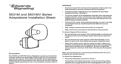
5540M Tone Generator 5532M Speaker Amplifier Sheet Adaptatone 5540M Tone Generator and 5532M Speaker Amplifier is intended for industrial applications where high audible output microcomputer reliability are required The Adaptatone Millennium are UL and cUL Listed as audible signal appliances for use in hazardous locations listed in Table 1 5532M Y6 is additionally UL Listed in a speaker and amplifier when powered with 120 240 VAC 50 60 Hz for use in with the 5541M Y6 Millennium System Master either for non fire or for supplementary fire alarm panel accessory applications See the installation and instructions for the 5541M Y6 P N 3100471 equipment is suitable for use in Class I Division 2 Groups A B and D Class II Division 2 Groups F and G Class III hazardous or nonhazardous locations Tone Generator operates from local power It accommodates up four normally open contacts on its inputs The tone that sounds in to an active input is determined by setting miniature switches inside the unit Table 6 has switch settings for tones tones may be programmed into the Tone Generator at any time tones operate on a pyramid type priority system The tone on SW1 overrides the tones programmed on SW2 SW3 SW4 The tone on SW2 overrides the tones programmed on SW3 SW4 Likewise the tone on SW3 overrides the tone programmed SW4 The tone programmed on SW4 has the lowest priority and override any other programmed tone Speaker Amplifier is a heavy duty stand alone signaling device operates from local power and sounds a tone programmed at the Generator Speaker direction and output level are easily Up to 2,500 Speaker Amplifiers can be connected in to the tone output of a single Tone Generator Adaptatone can be mounted on any flat surface or can be used as freestanding unit mounted on a rigid pipe The Adaptatone must be in accordance with the latest edition of the National Electrical NEC or other regulations applicable to the country and locality installation and by a trained and qualified electrician The increased resistance due to long wire runs needs to be for in sizing wire Consult Applications Engineering for Model numbers ending in AQ 24 VAC power must be transformer from mains or line power Explosion hazard Do not disconnect equipment unless power has removed or the area is known to be nonhazardous Explosion hazard Substitution of any components may impair for Class I Division 2 To ensure the integrity of the Adaptatone assembly when adjusting speaker direction make sure threads in the enclosure remain engaged and do not turn speaker more than 360 degrees the original factory installed position To prevent fire shock and component damage no work including board removal should be performed while the circuit is High voltage is present when product is energized High volume may cause harm to personnel in close proximity To ensure the integrity of the enclosure Ensure the cover gasket P 007549 0069 is adhered into groove at cover perimeter replacing the signal box cover Ensure that the four collar gaskets P N P 041930 0362 are in on each cover screw before securing the signal box cover When securing cover start screws by hand making sure they are into tapped holes in housing bosses before securing with screwdriver Torque signal box cover screws to a minimum of in lbs This ensures the required tight fit Any kind of service or maintenance performed while unit is will void the warranty install the Adaptatone Mount Adaptatone as shown in Figure 1 Surface mounting Secure the unit to the mounting surface the four mounting holes in the mounting plate on the rear of box Use the 10 x 3 wood screws furnished loose or other not supplied suitable for the mounting surface Pipe mounting Loosen the four cover screws from the box and lift off the signal box cover Cover screws are captive Do not remove them from the the center knockout in lower wall of the box and mount box on a 1 2 in 13 mm conduit pipe using a suitable Wire in accordance with the instructions in on page 2 Refer to Figure 15 and Table 6 and select the desired tones Set programming switches on the input board input connected to IN1 set on SW1 IN2 set on SW2 IN3 set SW3 and IN4 set on SW4 in order of the priority desired Adjust the volume level if desired by turning the potentiometer on the main board Figure 14 through Figure 17 and on voice board Figure 16 3100010 EN REV 09 ISS 14JAN15 10 Tightly secure the signal box cover using the four retained cover Wire as follows referring to Figure 4 through Figure 6 These Torque the signal box cover screws to a minimum of 20 in lbs To adjust the speaker direction the loosen large star nut Figure 1 turn the speaker to the approximate desired position the nut and turn the speaker slightly clockwise until it is into place of the speaker direction adjustment it is important that star nut be tightened wrench tight to ensure the speaker is maintained securely Verify operability 1 Mounting the Adaptatone Speaker Large star nut to adjust speaker direction Signal box Cover screws 4X Collar gaskets 4X Mounting plate 10 x 3 in 76 mm screws or other hardware suitable for the Raceway and connections not supplied to 1 2 in 13 mm surface hole To prevent fire and shock wire the Adaptatone only as described this installation instruction When wiring units with replaceable fuses ensure that an adequate suitable for the location is provided to remove power from fuse Remove power before servicing the fuse Terminal Block TB1 can be unplugged from the main board to wiring as shown in Figure 2 and Figure 3 wire the Adaptatone wires through a knockout hole in the bottom of the box from raceway that is with its connections to the 1 2 in 13 mm knockout hole approved for the same degree of protection enclosure type needed by the application Use the provided cable ties on the barrier to the electronics to separate power leads from signal and tone initiating leads per Figure 4 through Figure 6 apply to both tone generator and 5532M series except as noted Edwards Signal Actuator model number 5538 4 is used to initiate tones connect its four normally open switches to Tone Generator as shown on the instructions provided with the Actuator unit Connect the green and yellow striped earth ground wires to ground and additionally on the tone generator to the or drain of the audio cable in step b See Figure 5 and Figure 13 through Figure 16 Connect the output from the main board of the tone generator to AUD terminal on the Speaker Amplifier audio coupler Use shielded cable and connect the braid or drain to earth ground wire lead of the 5540 tone generator Up to speaker amplifiers can be so connected in parallel to a tone generator For the tone generator select the appropriate method for to the input board from Figure 7 through Figure 12 the tone generator as shown Connect the incoming power to the wire leads using a butt or other method listed certified or otherwise approved local authorities Leads are both black for AQ and N5 and are black and white for Y6 models Optional Connect an external 24 VDC battery not supplied in with the separate diode assembly P N 2600010 to TB1 terminals 3 and 4 on the main board as in Figure 3 and marked on the diode assembly Wire to the 5532B series Speaker Amplifier as follows and to Figure 4 through Figure 6 and Figure 17 Edwards signal actuator model number 5538 4 is used to initiate tones connect its four normally open switches to Tone Generator as shown on the instructions provided with the Actuator unit Connect the green earth ground wire of the Speaker Amplifier the green and yellow striped earth ground wires on the Generator to earth ground Connect the audio output from the main board of the Tone to the Tone In terminal 9 in the Connect the audio output from the main of the Tone Generator to the Tone In terminal 10 in Speaker Amplifier Up to 2500 speaker amplifiers can be connected in parallel to a