Edwards 5545M Installation Instructions

File Preview
Click below to download for free
Click below to download for free
File Data
| Name | edwards-5545m-installation-instructions-9321658407.pdf |
|---|---|
| Type | |
| Size | 786.31 KB |
| Downloads |
Text Preview
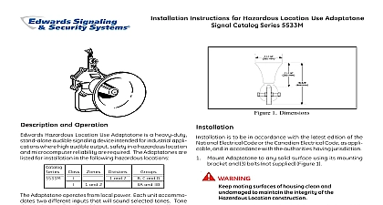
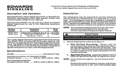
Series Adaptatone Installation Sheet 5545M Series Adaptatone Signals are intended for industrial where high audible output safety in a hazardous location microcomputer reliability are required 5545M Series speaker amplifiers are heavy duty signaling intended primarily for industrial signaling applications Each operates from local power and sounds a tone determined by the of a model 5540M Central Tone Generator or other source direction and output level are easily adjustable 5545M Series is UL and cUL listed for use in the hazardous shown in Table 2 equipment is suitable for use in Class I Division 1 Groups B C D Class I Division 2 Groups A B C and D hazardous locations General Signaling Service and wire this device in accordance with applicable national and codes ordinances and regulations and in a manner that is to the local authority having jurisdiction the device is used in general signaling applications you must it in accordance with these instructions and with the applicable of NFPA 70 in the US or CSA C22.1 in Canada the device is used in Division 2 applications you must install it in with the NFPA 70 Article 501 4b Explosion hazard Do not disconnect equipment unless power has removed or the area is known to be nonhazardous Explosion hazard Substitution of any components may impair for Class I Division 2 Explosion hazard Do not disconnect equipment while the circuit is or unless the area is known to be free of ignitable To prevent fire shock and component damage no work including board removal should be performed while the circuit is Keep the mating surfaces of the housing clean and undamaged to the integrity of the hazardous location construction Do not apply power to the unit until installation is completed and cover and outlet box cover are secured To prevent fire and shock do not connect power to the TS1 During installation take care not to damage components on printed circuit board install the signal Mount the signal on any solid surface using its mounting bracket three bolts not supplied See Figure 1 and Figure 2 Open the signal by removing the eight nuts and bolts and then off the housing cover Keep mating surfaces of the housing for proper reassembly Wire the signal as follows the signal label for the proper operating voltage Install the and tone wires through a 1 2 in conduit attached to an box and nipple outlet box conduit and nipple must be suitable for the location application with 1 2 14 NPT threading at the openings The outlet box conduit and nipple are not the cover from the outlet box Feed five numbered signal through a 1 2 14 NPT nipple not supplied into the outlet Secure the outlet box to the signal the green ground wire to earth ground the external wires to the signal wires as shown in 4 Polarity must be observed for DC applications Secure the outlet box cover The sound level is set to maximum at the factory Adjust the level if desired by turning potentiometer R72 Figure 2 Adjust the speaker direction by loosening the two nuts and pivoting speaker to the desired position Figure 3 Tighten the nuts Ensure that the mating surfaces are clean and undamaged the housing cover aligning the straight edge of the cover the straight edge of the housing Torque the nuts evenly in pairs to 140 in lb Apply power and verify the operability of the signal 2015 UTC Fire Security All rights reserved 4 3100795 EN REV 04 ISS 16JAN15 1 Signal dimensions 3 Speaker adjustment in mm in mm in mm Speaker adjustment nuts 2X 4 Wiring diagram 2 PC board and mounting holes in mm in mm Mounting holes 3X Speaker adjustment nuts 2X Potentiometer R72 for volume adjustment Housing nuts and bolts 8X each Housing cover VS GND 5540M Series Central Tone Generator Audio output board Wires 1 and 2 are signal and 4 and 5 are power AC or and AC or wire is for earth ground Power see Table 1 To earth ground To additional speaker amplifiers 2,500 max per installation 1 2 in conduit not supplied attached to outlet box Wire nuts 5X not supplied Conduit outlet box not supplied attached to Adaptatone 1 2 14 NPT nipple not supplied For connections to the input board refer to the instructions with the 5540M Central Tone Generator The outlet box conduit and nipple must be suitable for the location 4 3100795 EN REV 04 ISS 16JAN15 and testing Do not apply power to the unit until installation is and housing cover and outlet box cover are secured the unit semi annually for external accumulation of dirt Clean necessary Adaptatone should be tested annually or as required by the local having jurisdiction to ensure continuous service ambient temp Table 1 Table 1 lb 8.4 kg to 104 0 to 40 1 Electrical specifications VDC VAC 50 60 Hz VDC VDC VAC 50 60 Hz VAC 50 60 Hz A on 2 Hazardous locations location I Div 1 Groups B C and D I Div 2 Groups A B C D code 100 212 information 12.12.01 C22.2 No 30 C22.2 No 205 464 1203 1480 information contact information see www edwardssignaling com 3100795 EN REV 04 ISS 16JAN15 4 4 3100795 EN REV 04 ISS 16JAN15