Edwards 57EDF Series Installation Instructions

File Preview
Click below to download for free
Click below to download for free
File Data
| Name | edwards-57edf-series-installation-instructions-9068453721.pdf |
|---|---|
| Type | |
| Size | 598.05 KB |
| Downloads |
Text Preview
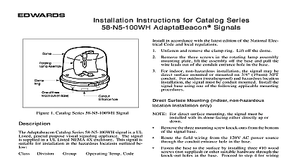
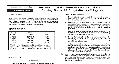
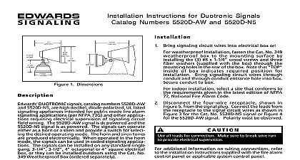
EDWARDS Instructions for 57EDF Series Heavy Duty Flash Strobe Lights mm 1 2 cid 147 mm 1 Dimensions Apply power to the unit and ensure proper operation 57EDF series signaling appliances are heavy duty double strobe lights intended for use in general signaling non fire applications The strobe lights are UL listed and CSA have a NEMA 4X enclosure and are available in 24V 120V AC and 240V AC See Table 1 for specifications 23 joule strobe is rated at 2.3 million peak candela Tube Replacement prevent electrical shock do not connect power installation has been completed and unit is assembled and secured this unit in accordance with the applicable requirements the latest edition of the National Electrical Code See the label and Table 1 for specifications For indoor applications the strobe light can be vertically either facing up or facing down outdoor applications the unit must be mounted with the lens facing up Pull appropriate power source wiring through 3 4 19 mm conduit Install the unit on the conduit Connect red positive lead to positive power source wire black negative lead to negative power source wire must be observed on 24V DC unit For AC units green ground wire to earth ground prevent electrical shock disconnect from the circuit and allow five 5 minutes for stored to dissipate before disassembling the unit the unit as follows Remove the four 4 screws from the lens assembly and the globe and lens as shown in Figure 2 prevent damage to the strobe tube hold the only by its base do not handle the tube Pry the strobe tube straight up and out of the strobe tube Refer to Table 1 for the correct replacement catalog number replace the strobe tube Assemble the unit Ensure that the o ring part number 044001 is in place the base of the unit and replace the lens and dome 2 CT 203 699 3000 FAX 860 677 7746 500003 ISSUE 3 1998 four 4 screws removed in step 1 After the unit is assembled apply power and ensure the unit properly Tube Ring 044001 Ring 044002 P late Screw s with washers securing dom e and lens base Tube Screw s with washers securing base plate base Conduit Hole 2 Replacing the Strobe Tube 1 Specifications Tube Hours Tube Parts Hours Hours Color 50 60 Hz DC No strobe tube life at operating power to 75 efficiency 50 60 Hz 500003 ISSUE 3