Edwards 7008B-N5 Installation Instructions
File Preview
Click below to download for free
Click below to download for free
File Data
| Name | edwards-7008b-n5-installation-instructions-6982715043.pdf |
|---|---|
| Type | |
| Size | 587.73 KB |
| Downloads |
Text Preview
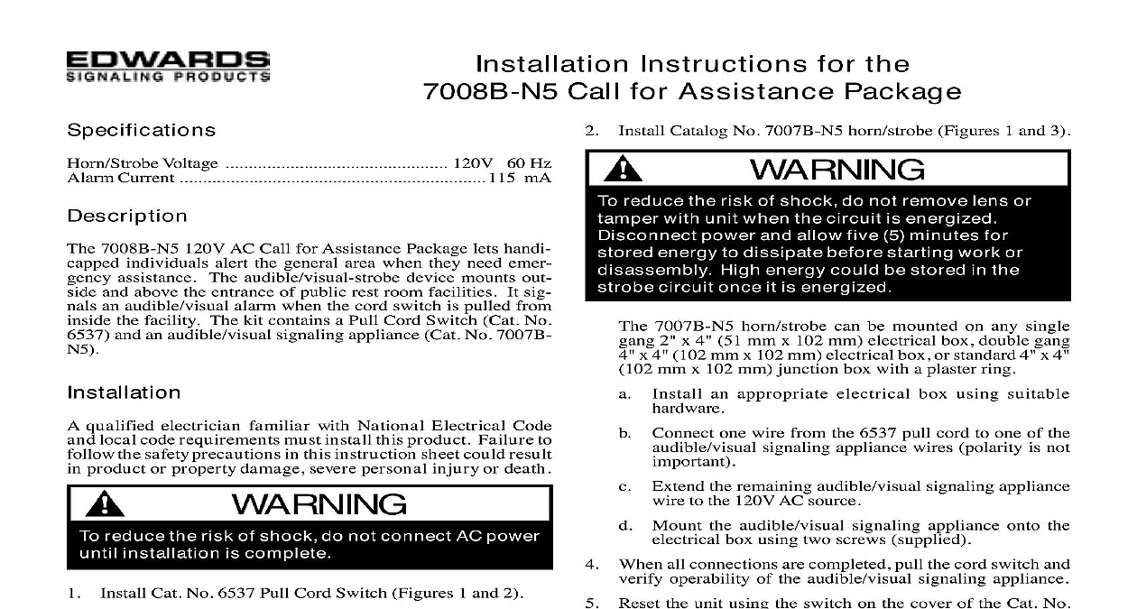
Installation Instructions for the Call for Assistance Package Catalog No 7007B N5 horn strobe Figures 1 and 3 Voltage 120V 60 Hz Current 115 mA 7008B N5 120V AC Call for Assistance Package lets handi individuals alert the general area when they need emer assistance The audible visual strobe device mounts out and above the entrance of public rest room facilities It sig an audible visual alarm when the cord switch is pulled from the facility The kit contains a Pull Cord Switch Cat No and an audible visual signaling appliance Cat No 7007B qualified electrician familiar with National Electrical Code local code requirements must install this product Failure to the safety precautions in this instruction sheet could result product or property damage severe personal injury or death reduce the risk of shock do not connect AC power installation is complete Cat No 6537 Pull Cord Switch Figures 1 and 2 a single gang 2 x 4 51 mm x 102 mm electrical using suitable hardware Extend the black and white wires using 18 AWG wire and not supplied Route the extended wires to horn strobe and transformer polarity is not important in accordance with local codes and regulations Mount the pull cord switch onto the electrical box using screws supplied an additional Catalog No 6537 pull cord switch is install a single gang 2 x 4 51 mm x 102 mm box Extend the black and white wires using AWG wire and connectors not supplied Route the wires to the previously installed pull cord switch connect the wire leads Figure 1 reduce the risk of shock do not remove lens or with unit when the circuit is energized power and allow five 5 minutes for energy to dissipate before starting work or High energy could be stored in the circuit once it is energized 7007B N5 horn strobe can be mounted on any single 2 x 4 51 mm x 102 mm electrical box double gang x 4 102 mm x 102 mm electrical box or standard 4 x 4 mm x 102 mm junction box with a plaster ring an appropriate electrical box using suitable Connect one wire from the 6537 pull cord to one of the signaling appliance wires polarity is not Extend the remaining audible visual signaling appliance to the 120V AC source Mount the audible visual signaling appliance onto the box using two screws supplied When all connections are completed pull the cord switch and operability of the audible visual signaling appliance Reset the unit using the switch on the cover of the Cat No Pull Cord Figure 2 regularly scheduled testing at least twice a year or more as dictated by local authorities having jurisdiction 7008B N5 Call for Assistance Package is not serviceable or Should it fail to operate properly contact the supplier replacement CT 203 699 3300 FAX 860 677 7746 ISSUE 1 1999 box for Pull Cord No 6537 cord switch FOR FOR box for Pull Cord 120V AC source 1 Connecting Catalog No 7008B N5 Call for Assistance Package for 3 4 mm FOR HELP 1 2 mm 120V AC 7007B N5 cord 9 16 mm 2 Catalog No 6537 Pull Cord Switch 120V AC source 6537 Pull Cord 1 2 mm ISSUE 1 4 Catalog No 7007B N5 Audible Visual Signaling Appliance