Edwards 867, 868 & 869 Installation Instructions

File Preview
Click below to download for free
Click below to download for free
File Data
| Name | edwards-867-868-869-installation-instructions-5620914378.pdf |
|---|---|
| Type | |
| Size | 970.71 KB |
| Downloads |
Text Preview
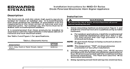
Installation Instructions for Electronic Horn Signal Catalog Series 867 868 and 869 horns are high quality signals intended for indoor or out use It is recommended that these products be installed accordance with the requirements in the latest edition of and local electrical codes For outdoor use the horns be installed with a weatherproof backbox Table 2 and Figure 1 for specifications 1 Horns Surface Mount Indoor Gray Surface Mount Outdoor Gray Flush or Panel Mount Indoor Gray horns are available in two voltages Insert suffix as N5 120V AC AQ 24V AC DC reduce the risk of shock do not connect AC or power to the horn until directed in these reduce the risk of shock always disconnect all before handling the unit Select a mounting method as detailed in Figure 1 and the electrical box using suitable hardware Be sure hook flange is facing outward as shown in 1 The designation TOP on boxes denotes of box after installation Attach mounting plate using two 8 32 screws provided the surface box or four 8 32 screws provided with box The flush box uses two 8 32 screws provided Bring the signaling circuit field wiring into electrical box 1 Mounting the Horn CT 203 699 3000 FAX 203 699 3365 CUST SERV 203 699 3078 TECH SERV ISSUE 3 2000 Connect the signaling circuit field wires to the terminals 2 and 3 Polarity must be observed for units operating 24 VDC Apply power and activate the horn unit to verify that it is properly Mount horn assembly on the mounting plate Figure 1 The inside of the top of the grille has hinges that pass cutouts and engage with tabs on the mounting With the bottom of the grille lifted out slightly the grille over the mounting plate so that the hinges the grille are in the mounting cutouts Properly seat the grille by pressing the bottom in Fasten the bottom of the grille to the mounting plate by the captive combination drive screw the unit fail to operate properly do not attempt Contact the supplier for replacement a visual inspection and an operational test twice a year 2 Wiring Diagrams 3 Terminal Block 2 Specifications Model Model AC 50 60 Hz AC 50 60 Hz DC mA mA mA Voltage Current Level Output at feet 3.05 m Chamber Environment 104F 40C relative humidity 32 to 120F 0 to variable ambient temperature dBA 104F 40C relative humidity 31 to 150F 35 to variable ambient temperature operating voltage to the horn may be continuous or coded such as march time or a pattern meeting ISO8201 ANSI S3.41 Audible Emergency Evacuation Signal ISSUE 2 d des appareils de signalisation s 867 868 et 869 klaxons sont des appareils de signalisation de haute qualit pour utilis l ou l Il est de toujours installer ces appareils conform la derni en vigueur des codes nationaux et locaux Les klaxons utilis l doivent sur une bo l des intemp le tableau 2 et la figure 1 pour les caract tech 1 Klaxons montage encastr l gris montage en saillie l gris montage l encastr ou sur gris klaxons sont disponibles en deux tensions Ins le pertinent N5 120V c a AQ 24V c a c c EN GARDE r le risque de choc ne mettez pas le sous tension c a ou batterie avant d avoir re dans la pr notice r le risque de choc d toutes sources d avant de toucher l Choisissez la m de montage voir la figure 1 et la bo au moyen des accessoires de appropri Le rebord d doit vers l illustr sur la figure 1 L ou sur les indique l de la bo une fois Fixez la plaque de montage au moyen des deux vis no 8 fournies avec la bo de montage en saillie ou les vis no 8 32 fournies avec la bo La bo utilise deux vis no 8 32 non fournies 1 Fixation du klaxon CT 203 699 3000 FAX 203 699 3365 Service la client 203 699 3078 Service technique 3 2000 Tirez l de la bo les fils externes du Fixez le bas de la grille sur la plaque au moyen de la vis de signalisation Raccordez les fils du circuit de signalisation aux bornes du figures 2 et 3 en respectant la polarit si l sur 24 V c c Mettez l sous tension et d pour v fonctionne correctement Fixez le klaxon sur la plaque de montage Fig 1 Le haut de la grille comporte l des charni passent dans les fentes et s avec les pattes fixation sur la plaque de montage Soulevez le bas de la grille et placez la sur la plaque montage de fa ce que ses charni s les fentes de la plaque de montage Appuyez sur le bas de le grille pour la mettre en place EN GARDE l ne fonctionne pas correctement n de le r Adressez vous au fournisseur pour un appareil de rechange visuellement l et v son fonctionnement fois par an 2 Sch de c 3 Bornier 2 Caract techniques de fonctionnement c a 50 60 Hz c a 50 60 Hz c c de fonctionnement mA mA mA N5 AQ sonore 10 pieds m Chambre an dBA ambiantes l d relative 104 40 temp de 32 120 0 49 l d relative 104 40 temp de 31 150 35 66 tension de fonctionnement appliqu au klaxon peut continue ou cod p ex Suivant la de marche ou suivant la cadence temporelle conforme l 8201 ANSI S3.41 sonore d d 3