Edwards 870 Series Indoor - Installation Instructions

File Preview
Click below to download for free
Click below to download for free
File Data
| Name | edwards-870-series-indoor-installation-instructions-4356978210.pdf |
|---|---|
| Type | |
| Size | 582.24 KB |
| Downloads |
Text Preview
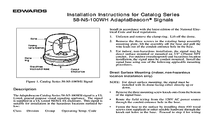
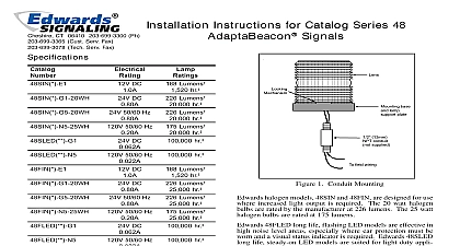
Installation Instructions for AdaptaHorns AdaptaHorns are UL listed vibrating horns They are low high decibel horns designed for heavy duty use indoors horns are intended for general signaling applications Compatibility electrical input load requirements for PLC compatible sig devices are listed in Table 1 Signaling devices may be connected to output cards that meet these input load re DC electromechanical horns such as the 871 G1 873 G1 and 875 G1 can produce transient spikes and should be used on PLC output cards that have inherent transient suppression The Process Control Engineer should consult PLC manufacturer when connecting 24V DC electromechani devices to PLCs Mounting 870 and 871 Series Using approved wiring methods connect black wire leads to source wires Polarity is not important Ground to wiring system horn connector into connector receptacle and secure to backbox with 4 oval head screws supplied Mounting 872 872DPO 873 873DPO 874 and 875 Loosen screw at bottom of horn and remove backplate Mount plate using one of the following methods Mount on any outlet box cover having single gang using 6 screws supplied Mount on a 3 1 4 83mm 3 1 2 89mm 4 102mm or 4 102mm square box using 8 screws with backbox Mount on the wall for open wiring using 8 wood screws Using approved wiring methods connect one wire to each in backplate Ground to wiring system Place the horn on the mounting plate so that the tab at the top in slot on horn Press horn firmly against plate and screw at bottom of unit See Figure 1 AC DC AC AC DC DC AC DC No AC volts at 60 Hz 1 PLC Compatibility off state current mA on mA inrush duration CT 203 699 3000 FAX 860 677 7746 ISSUE 1 1999 1 Mounting the Horn on the AdaptaPlate Adjustment devices have a volume adjustment screw located on the front factory set to maximum To reduce volume level set screw clockwise using the supplied 1 16 1.6mm allen 2 Electrical Specifications No 50 60 Hz 50 60 Hz 50 60 Hz DC DC DC DC DC 50 60 Hz 50 60 Hz 50 60 Hz 50 60 Hz 50 60 Hz 50 60 Hz 50 60 Hz DC DC DC DC DC DC DC DC DC 50 60 Hz 50 60 Hz 50 60 Hz 50 60 Hz DC DC DC DC DC DC ISSUE 1