Edwards 96B, 98B, 99B Series Installation Instruction

File Preview
Click below to download for free
Click below to download for free
File Data
| Name | edwards-96b-98b-99b-series-installation-instruction-8245693017.pdf |
|---|---|
| Type | |
| Size | 783.51 KB |
| Downloads |
Text Preview
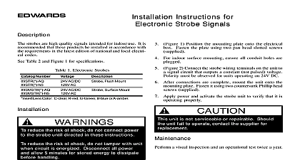
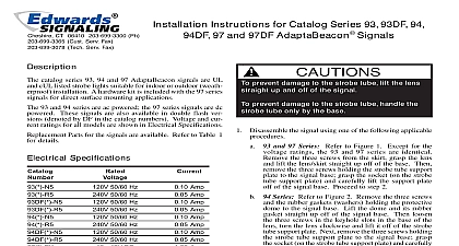
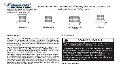
EDWARDS Instructions for Catalog Series 96B and 99B AdaptaBeacon Signals Specifications NUMBER VOLTAGE 50 60 Hz 50 60 Hz Amp Amp Amp Amp Amp Amp color of lens by adding one of the following letters to catalog number A amber B blue C clear G green or R red units are UL Listed with the exception of the 99 E1 Information Catalog Series 96B 98B and 99B Adaptabeacon signals small strobe lights suitable for indoor or outdoor weath installation Catalog Series 96B and 98B are UL listed in NEMA 4X enclosures 96B and 98B series signals are designed for mounting on 13mm NPT conduit The 96B and 98B series signals also be direct surface mounted The 98B series signals supplied with a hardware mounting kit for direct surface For outdoor weatherproof installation the 96B 98B series signals must be conduit mounted with their facing directly up When installing indoors these sig can be mounted in any position The 96B series signals AC powered the 98B series are DC powered Each series several models with different operating voltages 99B series signals come with a magnetic mounting disk their base and a 7 1 2 foot 2.29m cord with cigarette adapter plug These signals can be attached to any surface and are ideal for temporary mounting on vehicle dashboards or rear decks A steel circular disk is supplied with the 99B series signals to a steel surface for vehicles with non magnetic sur such as dashboards A fabric hood is also included with signals which may be attached to the signal when it is inside the vehicle to shield the vehicle occupant from the strobe light The 99B series are 12V DC pow 1 Conduit Mounting of the 96B 98B Series Signals the signals using one of the following mounting proce prevent electrical shock ensure that power is before installing the signal prevent leakage and a potential shock hazard mounting outdoors the signal must be with the lens or dome facing directly up and 98B Series Signals Conduit Mounting Refer to Figure 1 The signals require 1 2 13 mm NPT not supplied Route the wire leads from the signal through the conduit Refer to the signal label for the rating Thread the conduit into the signal mounting CT 203 699 3000 FAX 860 677 7746 ISSUE 5 1998 and 98B Series Signal Direct Surface When installing indoors the 96B and 98B series may be mounted in any position 96B series signals are not supplied with a direct mounting kit but can be direct surface mounted using appropri hardware a small flat blade screwdriver between the locking and the lens Gently push down and then pry unseating the lens Pull the lens up and off of the signal base being careful not to damage the lamp Refer to Figure 2 Remove the two knockouts for the screws from the signal base Place the 3 3 4 mounting gasket provided in the direct surface hardware kit on the mounting surface and mark center of the three holes in the gasket on the surface the mounting gasket and drill a 3 8 10mm hole each of the marked positions the two rubber expansion plugs provided in the kit into the two outer holes in the mounting surface indicated in Figure 2 Route the wire leads from the signal base through the center in the mounting gasket and mounting surface Refer to signal label for voltage rating Align the outer holes in the mounting gasket with the holes the surface Insert the two screws with lockwashers in the hardware kit through the two outer holes in signal base and align the screws with the rubber expansion as shown in Figure 2 Press the signal base firmly the mounting surface and tighten the screws and 98B Series Signals Wiring Connect the field wiring to the signal wiring using one of following applicable procedures Series Using wire nuts not supplied connect the wiring to the signal wire leads as shown in Figure 1 is not important Insert the wires into an appropriate junction box not supplied Series Using wire nuts not supplied connect the red positive wire lead to the positive power source and connect the signal black negative wire lead to negative power source wire Polarity must be observed the wires into an appropriate electrical junction box supplied Series Signals Magnetic Mounting prevent damage or loss using the signal out of the vehicle during high speed driving is not recommended magnetic surfaces To mount the 99B series signals on a surface simply mount the signal where required and insert adapter plug into the vehicle cigarette lighter socket To possible scratching of the vehicle surface when installing removing the signal tip the signal slightly before making or magnetic contact with the surface 2 Direct Surface Mounting of the Series Signals 3 Mounting the 99B Series Signal on a Surface ISSUE 5 surfaces Refer to Figure 3 A steel circular disk supplied with the 99B series signals to provide for mounting signal to non magnetic horizontal surfaces as dashboards disk has a piece of Velcro permanently affixed to one side A piece of paper backed Velcro is attached to the disk Velcro Remove the paper backed Velcro from the disk Velcro and remove its paper backing Press the sticky side of Velcro onto the dash or other suitable surface Next attach disk Velcro assembly to the Velcro on the dash the 99B signal on the steel circular disk of the disk Velcro and insert the adapter plug into the vehicle cigarette socket dismount the signal remove the adapter plug from the ciga lighter Next to prevent removing the disk Velcro assembly removing the 99B signal press down firmly on the edge of disk assembly the assembly is slightly larger than the mag mounting base and tip the signal slightly before breaking contact with the disk and 98B Signals If the strobe light fails to operate make there is power to the signal If there is power and the strobe fails to operate replace the strobe tube as directed in the Tube Replacement section Signals If the strobe light fails to operate Verify that the adapter plug is firmly inserted into the cigarette socket Rotate the adapter plug a few times to remove possible ash from the contacts in the cigarette lighter socket the strobe still fails to operate remove the fuse for the lighter and clean the socket and contact surfaces the fuse and check the signal again the strobe still fails to operate replace the strobe tube as di in the Tube Replacement section prevent electrical shock ensure that power is before installing the signal prevent leakage and potential electrical shock care when disassembling the signal to prevent of the permanently affixed gaskets provided weatherproofing prevent damage to the lens do not use abrasive or cleaners clean the Adaptabeacon lens surface to maintain op light visibility The lens may be cleaned with a soft cloth sponge using water or a mild detergent solution Ensure that lens is completely dry before assembling the signal Tube Replacement to the Parts section below for the required of strobe tube After disconnecting power replace the strobe as follows to Figure 4 a small flat blade screwdriver between the locking and the lens Gently push down and then pry unseating the lens Pull the lens up and off of the signal base being careful not to damage the lamp prevent damage to the strobe tube handle the only by the base 4 Strobe Tube Replacement Series Signals ISSUE 5 PARTS Number Amber Blue Clear Green Magenta or Red Tube color of lens by adding one of the following letters to the catalog number B blue C clear G green M magenta or R