Edwards 96DV2 Series Installation Instructions

File Preview
Click below to download for free
Click below to download for free
File Data
| Name | edwards-96dv2-series-installation-instructions-4719362580.pdf |
|---|---|
| Type | |
| Size | 660.18 KB |
| Downloads |
Text Preview
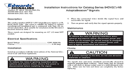
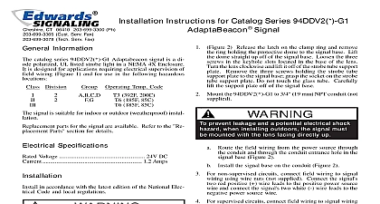
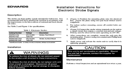
EDWARDS Instructions for Catalog Series 96DV2 N5 Signals catalog number 96DV2 N5 AdaptaBeacon signal is a UL small strobe light The signals are suitable for indoor or weatherproof installation and have type 4X enclosure They are suitable for installation in the Division 2 listed in Table 1 signals are designed for mounting on 1 2 13 mm NPT Specifications Voltage 120V 50 60 Hz 0.10 Amp in accordance with the latest edition of the National Elec Code and local regulations reduce the risks of igniting hazardous atmo and electric shock ensure that power is before installing the signal prevent leakage and a potential shock hazard mounting outdoors the signal must be with the lens or dome facing directly up Refer to Figure 1 The signals require 1 2 13 mm NPT not supplied Route the 18 457 mm wire leads from the bottom of the signal mounting base through conduit Thread the conduit into the signal mounting Using wire nuts not supplied connect field wiring to signal Connect the green ground wire leads using wire nuts supplied Insert the wires into an appropriate electrical box the strobe light fails to operate make sure there is power to the If there is power and the strobe still fails to operate re the strobe tube as directed in the Strobe Tube Replacement prevent damage to the lens do not use abrasive or cleaners clean the AdaptaBeacon lens surface to maintain light visibility The lens may be cleaned with a soft or sponge using water or a mild detergent solution Ensure the lens is completely dry before assembling the signal Tube Replacement reduce the risks of igniting hazardous and electric shock ensure that power disconnected before installing the signal Do not power until installation has been and unit is tightly assembled and prevent leakage and a potential shock hazard care when disassembling the signals to tearing of the gaskets to Table 2 for the required strobe tube Refer to Figure 2 Remove the screw in the clamp ring ring and set aside Carefully lift the lens straight up off the signal mounting base being careful not to damage strobe tube or lens gasket If the lens adheres to the gasket the signal base do not force apart by hand but carefully the lens off using a thin blade screwdriver prevent damage to the strobe tube handle the tube only by the base Grasp the strobe tube by its base and pull straight up from its Install the new strobe tube by aligning the connector the base of the tube with the mating socket Carefully down into the socket Assemble the signal Turn on power and verify that the strobe operates letter in this position signifies the color of the supplied lens A amber B blue C clear G green M magenta or R red CT 203 699 3000 FAX 860 677 7746 ISSUE 4 1998 1 Division 2 Locations B C D G Code 160 320 85 185 85 185 2 Replacement Parts Number or Number tube letter in this position A amber B blue C clear G green M or R red signifies the color of the lens for example a red lens for 94DV2 series signal is 93 LR 1 Conduit Mounting 2 Strobe Tube Replacement ISSUE 4