Edwards ANSX Expander Amps Install

File Preview
Click below to download for free
Click below to download for free
File Data
| Name | edwards-ansx-expander-amps-install-6314592708.pdf |
|---|---|
| Type | |
| Size | 751.30 KB |
| Downloads |
Text Preview
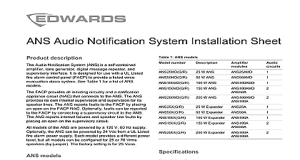
Expander Installation Sheet models use multiple amplifier configurations These are configured and prewired at the factory 1 ANS and ANSX models number W ANS W ANS W ANS W ANS W ANS W Expander W Expander W Expander ANS100A W Expander ANS100A W Expander ANS100A specifications and installation instructions see the ANS Notification System Installation Sheet P N 3101179 switch settings 1 shows the position of the terminal blocks jumper and switches on the ANSX Tables in this section the SN1 DIP switch settings for master and slave All other ANSX terminal assignments and jumper are the same as those on the ANS description Expander ANSX is a self contained amplifier tone power supply and supervisory interface It is for use with the ANS25 ANS50 and ANS100 to provide additional speaker output power ANSX can also be used as a stand alone audio system for fire alarm control panel FACP to provide voice evacuation an automatic message is not required and operation of the ANSX is identical to the ANS the ANS Audio Notification System Installation Sheet 3101179 with the exception that the ANSX does not digital messaging Table 1 for a list of ANSX models used in conjunction with an ANS the ANSX acts as a reproducing the tone and message generated by the When used as a stand alone the ANSX connects to FACP exactly as the ANS does to provide automatic tone alarm and voice override capability terminal designations and volume controls are identical to ANS On the ANSX SN1 determines tone master slave and microphone settings There is no SN2 models model numbers have the format ANS999MDC Each is a complete audio notification panel including a built in generator power transformer and cabinet The 999 portion the output power 25 50 100 150 or 200 watts indicates the inclusion of a microphone D indicates the of a digital message repeater DMR C indicates the color either gray G or red R model numbers have the format ANS999XC Each is a complete expander panel including a built in tone power transformer and cabinet The 999 portion the output power X indicates an expander module have no microphone and no DMR C indicates the color either gray G or red R model numbers have the format AMS999AMD The include a built in tone generator but no transformer cabinet The 999 portion represents the power output The A indicates an amplifier M indicates the inclusion of microphone D indicates the inclusion of a digital message Expander can operate as a slave amplifier when connected an ANS999AMD which supplies source audio to the slave can also operate as stand alone audio notification with only tone and microphone amplification 2013 UTC Fire Security All rights reserved 4 3101180 REV 02 REB 28FEB13 1 Terminal and jumper block positions 2 3 25V yellow green red switch detail 2 3 4 5 6 7 8 settings 2 and Table 3 show the factory settings when the ANSX used as a slave unit or as a master unit 2 Slave unit settings Description whoop signal used as primary generator disabled connected microphone 3 Master unit settings Description whoop signal see Table 4 used as primary generator enabled connected connected settings the ANSX is used as a master unit SN1 1 2 and 3 the generated amplifier tone 4 Tone settings for master unit the evacuation tone There are eight Off Off Temporal whoop Off Off Hi lo tone On Off Sine wave Off On 1 kHz sine wave On Off March time 880 Hz Off On Slow whoop On On Code 3 beep 4 3101180 REV 02 REB 28FEB13 diagrams 2 Wiring for typical stand alone application ALARM CONTROL PANEL shown in alarm and power limited and power limited POWER 120 Vac and nonpower limited and power limited B Style Y life safety speakers Break the wire at all terminals to maintain supervision Do not the wire around the terminals A Style Z fire only and power limited 2 3 25V yellow green red EOLR EOLR CIRCUIT wire harness current 1 A max and nonpower limited V V wire provided 3101180 REV 02 REB 28FEB13 4 3 Wiring detail for master to slave connection shown in alarm ADDITIONAL 1 yellow green red 2 3 and power limited yellow green red 2 3 25V ANSX 2 and power limited ANSX The maximum number of units that can be cascaded is 15 Switch SN1 1 through 6 and SN1 8 must be OFF for slave units All power supervisory and speaker connections remain Unsupervised wiring must be in the same cabinet or in conduit cabinets that are in the same room and within a distance of 20 feet A 14 pin ribbon cable factory supplied can be used in place of J1 jumpers must be removed from slave units for pass through connections 4 3101180 REV 02 REB 28FEB13