Edwards Appendix-Machine Safeguarding pg 88-93

File Preview
Click below to download for free
Click below to download for free
File Data
| Name | edwards-appendix-machine-safeguarding-pg-88-93-0621739548.pdf |
|---|---|
| Type | |
| Size | 2.30 MB |
| Downloads |
Text Preview
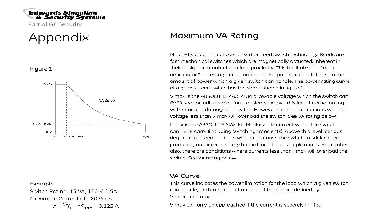
Appendix VA Rating 1 V at IMAX V Curve I at VMAX Rating 15 VA 120 V 0.5A Current at 120 Volts VA V 15 120 0.125 A Voltage at 0.5 Amps VA A 15 0.5 30 V Edwards products are based on reed switch technology Reeds are mechanical switches which are magnetically actuated Inherent in design are contacts in close proximity This facilitates the circuit necessary for actuation It also puts strict limitations on the of power which a given switch can handle The power rating curve a generic reed switch has the shape shown in figure 1 max is the ABSOLUTE MAXIMUM allowable voltage which the switch can see including switching transients Above this level internal arcing occur and damage the switch However there are conditions where a less than V max will overload the switch See VA rating below max is the ABSOLUTE MAXIMUM allowable current which the switch EVER carry including switching transients Above this level serious of reed contacts which can cause the switch to stick closed an extreme safety hazard for interlock applications Remember there are conditions where currents less than I max will overload the See VA rating below Curve curve indicates the power limitation for the load which a given switch handle and cuts a big chunk out of the square defined by max and I max max can only be approached if the current is severely limited max can only be approached if the voltage is severely limited load power rating for GE Interlogix Industrial switches is always stated Volt Amps In DC applications Volts times Amps always yields power Watts However in AC applications this is true only with a unity Power In general for AC applications apparent power exceeds real power Power is measured in Watts Apparent Power is measured in Volt Amps Protection Circuits Applications TransZorb back to back diodes parallel switch Circuits Inductive Loads the GuardSwitch is applied in a circuit that has an inductive device such as a relay solenoid or contactor the stored in that device will provide an inverse voltage to the when the interlock opens If this inductive back EMF the electrical rating of the switch a protection circuit is required prevent premature interlock failure Two recommended protection for inductive loads are shown in Figure 1 Circuits Capacitance Loads loads or long cable runs that exceed 50 feet are prone to high currents which if they exceed the electrical rating of the switch will premature interlock failure This inrush can be reduced by a resistor shown in the circuits in Figure 2 Circuits Lamp Loads lamp loads are a less obvious source of transient surges are equally damaging to the interlock Cold lamp filaments can have resistance 10 times smaller than already glowing filaments causing inrush 10 times greater than the steady state current If the inrush exceeds the electrical rating of the GuardSwitch a protection such as illustrated in Figure 3 should be used Triac 8 18 E DT can switch up to 150 VA without added protection 1 Applications protection diode in with load Figure 2 Load R should be so the ratings be obtained wattage be matched the circuit and voltage drop be considered Capacitance Figure 3 R should be so the switch may be obtained wattage must matched to the circuit the voltage drop be considered 1 2 3 4 5 1 1 2 2 A B C Switch Assembly assembly begins with the special forming of the magnetic wires to them the proper shape and flexibility Next the blades are plated with ruthenium tungsten or gold to give them a very hard surface good electrical conductivity Two of the reed wires are then critically in a small glass tube A nitrogen gas stream is directed through tube as heat is applied to the upper end of the tube The heat melts tip of the tube around the wire to form a seal The heat is moved to other end of the tube and it too is melted to form the second seal The seal secures the second wire and forms a hermetic seal with the tube filled with nitrogen See Figure 1 Switch Types are three different types of reed switches in general use They are A two wire normally open Form B two wire normally closed and C three wire normally open and normally closed Form C reeds are called single pole double throw SPDT switches A Normally Open N O A reeds are switches that are normally open when there is no field near them and closed when a magnet is in proximity The open title is the common electrical description for switches non actuated condition is open switch contacts are not touching no electrical current can flow See Figure 2 B Normally Closed N C B reeds are switches that are normally closed when there is magnetic field near and open when a magnet is in proximity The closed title is the common electrical description for switches non actuated condition is closed See Figure 3 C Single Pole Double Throw SPDT C reeds are switches that can be either normally open or normally Form C switches have three wires the center or Common wire normally closed wire and the normally open wire In the non actuated current flows in the common wire and out the closed wire as in Form B above In the operated condition the common element from the closed wire to the open wire allowing current to from common to the normally open wire as noted in the Form A above See figure 4 Pole Double Throw DPDT Pole Double Throw contacts are created by assembling two Form reeds in the same switch housing DPDT contacts can be used in circuits perform separate functions at the same time The two switches have sense ranges Usually one contact is connected to the safety and the second switch is connected to an indicator or status light Figure 5 Wires Tube Gas 1 2 Pole Double Throw Switch Assembly Switch Sensitivity gap distance noted for a reed contact is the distance between the magnet and the contact when the reed operates Gap distance defined by the size of the magnet and reed sensitivity Reed sensitivity measured in terms of how much magnetism it takes to operate the and is measured in ampere turns To explain electrical current through wire creates a magnetic field around the wire When this is wrapped around a reed switch the magnetism is felt by the reed to the number of turns around the reed Therefore amps the wire times the number of turn equals amp turns Standard reed are 10 to 70 amp turns for safety and position switches Wide contacts have reed sensitivities of 6 to 10 amp turns In the last few reed switch manufacturers have been able to supply reliable Form A that meet the wide gap sensitivity requirements which has allowed cost wide gap contacts Reed manufacturers have not been able manufacture high sensitivity Form C reeds therefore wide gap and contacts are created by performing a wide gap operation during assembly The wide gap operation is accomplished by gluing a magnet to the reed to give it a boost in sensitivity Wide gapping a causes the contact to become polarity sensitive When mounting a gap Form B and C contacts the installer must insure that the actuator is installed observing proper polarity terms that are associated with switch gap are make break differential is the term used to note switch actuation and usually to the gap distance between the switch and magnet when the operates is the term used to note switch deactivation or out also is used on reference to switch magnet gap when the opens is distance between switch gap at make and the switch gap break This is also known as the hold distance or hysteresis and it can a significant distance with some
