Edwards B-8313 Installation Instructions

File Preview
Click below to download for free
Click below to download for free
File Data
| Name | edwards-b-8313-installation-instructions-7401389526.pdf |
|---|---|
| Type | |
| Size | 697.70 KB |
| Downloads |
Text Preview
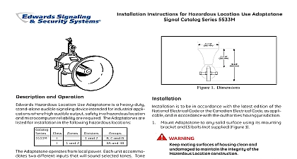
Installation Instructions for Catalog Numbers B 8313 B 8316 B 8319 B 8320 B 8322 B 8323 and B 8325 Telecode Relays devices are intended for connection to single telephone or key systems only When installed in accordance with these instructions devices can be readily disconnected without equipment remaining on the telephone with the Federal Communications in compliance with Part 68 of FCC Rules Regulations UL Listed Type NM non monitored signal device company will notify the owner that it may tempo disconnect service if they consider such action nec If the owner considers the disconnection unwar they have the right to bring a complaint to the telephone company may make changes in its commu facilities equipment operations or procedures such action is required If these changes render the incompatible with the telephone company facili the telephone company will provide enough written so that necessary changes can be made in order to uninterrupted service Edwards mechanical telephone relays are designed use with horns bells strobes or similar devices to remote telephone ringing capability in areas where noise levels are high or personnel are unable to near telephones at all times The relays can operate to five vibrating type horns buzzers and bells and not affect the efficiency of the phone The panel pressed steel and Hazardous Location units are Listed for indoor use and the weatherproof units are Listed for outdoor use panel mount unit has a steel cover on a 4 1 4 diam bakelite base The pressed steel unit has a hinged cover and 1 2 and 3 4 knockouts The weather unit has a cast back box with a threaded joint for a aluminum enclosure The Hazardous Location unit a cast box with a dust tight flame proof joint and is for 1 2 conduit The Hazardous Location unit is Listed for Class I Group D and Class II Groups F and G cid 15 cid 2 cid 16 cid 2 cid 7 cid 17 cid 9 cid 10 cid 2 cid 14 cid 11 cid 10 cid 18 cid 9 cid 5 cid 12 cid 13 cid 8 cid 6 cid 9 cid 10 cid 9 cid 10 cid 4 cid 11 cid 8 cid 12 cid 9 cid 8 cid 13 cid 10 cid 5 cid 12 cid 7 cid 8 cid 14 cid 5 cid 12 cid 15 cid 8 cid 16 cid 17 cid 3 cid 17 cid 16 cid 5 cid 12 cid 9 cid 18 cid 19 following information may be required by the tele company Telephone Number FCC Registration 329USA 21458 RG N Ringer Equivalence Num REN 3.4B REN allows the installer to determine the number of that can be added to the telephone line and still all the devices ring when the number is called In but not all areas the sum of all RENs for all de connected to your line should not exceed five To sure of the number of devices you can connect to your line contact your local telephone company these devices damage the telephone network the tele Telecode Relays Coil With Capacitor Without Capacitor AC AC DC Mfd Capacitor with Bracket No MOUNT UNITS Without Capacitor Normally Open STEEL UNITS Without Capacitor Normally Open With Capacitor Normally Open UNITS Without Capacitor Normally Open With Capacitor Normally Open LOCATION UNITS Without Capacitor Normally Open With Capacitor Normally Open Units with capacitors are FCC certified 2500 and 3000 ohm coils available To order 1000 in Cat No to appropriate resistance shading coils prevent armature chatter Relay coil are rated in ohms Wire size and number of vary with resistance requirements of units is 1 cid 1 F at 400V except panel mount which require remote capacitors AC relays and re used on common battery circuits require capacitors relays do not require capacitors unless energized by a battery are made from tungsten and are rated at 8 amps 110V DC CT 203 699 3300 FAX 203 699 3365 CUST SERV 203 699 3078 TECH SERV ISSUE 3 2001 cid 8 cid 9 cid 14 cid 25 cid 9 cid 12 cid 12 cid 26 cid 10 cid 6 cid 4 cid 13 cid 8 cid 6 cid 9 cid 10 cid 3 cid 14 cid 25 cid 6 cid 5 cid 4 cid 26 cid 6 cid 8 cid 3 Series B 8313 B 8315 and B 8316 B 8319 and B 8320 B 8322 and B 8323 are intended for installations where of the following conditions apply The product is electrically isolated from cable outside the building Cable that this product is not electrically isolated is not outside a building for more than 1000 and is in conduit that is buried in a trench has been separated from lines The product is installed as a component of a system network that is i UL to UL 1950 or CSA Certified to C22.2 No as deemed acceptable to the authorities jurisdiction and ii installed according to applicable Listing and or Certification Series B 8319 B 8320 B 8322 and B 8323 are also in for installations where the product is not isolated cable outside the building and either the product or the communications system network that the prod is part of is protected by Protectors that i limit cur energy to no greater than 100 A2 s and limit current no greater than 1.3A and ii are UL Listed to either UL 497A or CSA Certified to C22.2 No 226 as acceptable to the authorities having jurisdiction enclosures of the B 8319 B 8320 B 8322 and B 8323 are Fire Enclosures as defined in UL Standard 1950 of Information Technology Equipment that can be by turning the threaded cover counterclockwise loosen and remove or closed by turning the threaded clockwise to tighten and secure cid 21 cid 22 cid 23 cid 11 cid 23 cid 24 not connect units without capacitor to telephone lines Figures 2 through 4 for relay dimensions Refer to Table 1 for voltage selection Wire telephone line to relay as shown in Figure 1 Verify operability of mechanical relay 1 Wiring Diagram terminals accept 26 12 AWG wire size 2 Weatherproof and Explosion Units ISSUE 3 2 3 Relay in Pressed Steel Enclosure 4 Panel Mount Relay 3 ISSUE 3