Edwards B4U Analog Standard Detector Base Installation Sheet

File Preview
Click below to download for free
Click below to download for free
File Data
| Name | edwards-b4u-analog-standard-detector-base-installation-sheet-2405189763.pdf |
|---|---|
| Type | |
| Size | 1.19 MB |
| Downloads |
Text Preview
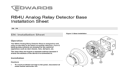
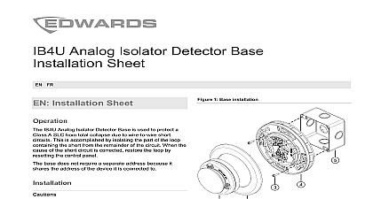
Analog Standard Detector Base Sheet FR Installation Sheet B4U Analog Standard Detector Base provides mounting and electrical connections for the compatible detectors in Specifications base does not require a separate address base comes with an adaptor bracket and trim ring for use a 4 in square electrical box are two ways to install the B4U base assembly Option 1 Use an octagon or single gang electrical box Option 2 Use a 4 in square electrical box install the B4U using option 1 Pull the wiring into the box and through the hole in the an octagon or single gang electrical box of the detector base Attach the detector base to the electrical box using the provided with the electrical box Make wiring connections as shown in Figure 3 Apply power and activate the unit to verify that it is 1 Base installation option 1 Octagonal electrical box B4U base assembly Screws install the B4U using option 2 Pull the wiring into the box and mount the adapter bracket a 4 in square electrical box comes with the B4U Pull the wires through the hole in the detector base and the detector base to the electrical box using the bracket and the screws provided with the box See Figure 2 Attach the trim ring by aligning the arrows on the trim ring those on the base and pressing down to lock the trim into place Make wiring connections as shown in Figure 3 Apply power and activate the unit to verify that it is Attaching the trim ring to the detector can occur before after assembling the detector to the base 2013 UTC Fire Security All rights reserved 4 3101074 REV 05 REB 25JAN13 2 Base installation option 2 3 Base wiring option 2 installation shown in square electrical box Adaptor bracket B4U base assembly Trim ring Aligning arrows in accordance with NFPA 72 or CAN ULC S524 Be sure observe the polarity of the terminals on the terminal block as in the diagram the wire run at each terminal Do not loop signaling field wires around terminals To avoid accidental damage to the panel disconnect power before wiring the unit If shielded cable is used the following recommendations wire is required only in environments with very electrical noise Use of shield connections must be continuous and must insulated from ground Electrical tape is recommended a minimum to insulate the shield Class B wiring all shields must be continuous and from ground except at the originating panel From previous device or controller Optional trim ring Optional bracket Maximum resistance per wire must not exceed 10 To next device Description in and out in used Description used LED LED SLC out diameter trim ring trim ring from box including distance size detectors electrical boxes in 110.49 mm in 152 mm in 53 mm less than 4 in 100 mm from the 4 and 12 in 100 and mm from the ceiling to 18 AWG wire 0.75 to 2.5 mm E PD FX PHD E PHD E HD V PS V PHS V HRD V HFD 4 in octagonal ring mud box in 47 mm deep single gang in square x 2 1 2 in 64 mm deep requires using the included bracket and trim ring environment humidity temperature range to 120 0 to 49 to 93 noncondensing to 140 to 60 4 3101074 REV 05 REB 25JAN13 information Edwards A Division of UTC Fire Security Americas Inc Town Center Parkway Bradenton FL 34202 first two digits of the date code located on the identification label are the year of Part 15 Subpart J Class B DOC Class MDC B UL 268 UL 521 CAN ULC S529 09 of information contact information see our Web site Fiche D base analogique standard B4U pour d fonctionne les d compatibles r la section Fiche technique base n pas une adresse s base vient avec une parenth d et un anneau pour l avec les 4 po bo carr 1 Option 1 d de la base base de B4U Bo octogonale Vis installer le B4U utilisant l 2 Tirez le c dans la bo et par la parenth une bo qui est 4 po carr qui vient avec le B4U Attachez la base de d dans la bo la parenth d et les vis fournies par la Voir la Figure 2 Alignez les marques sur l de garniture avec celles la plaque de la base pressez l dans la plaque faites pivoter l jusqu ce qu se verrouille en les rapports de c suivant les indications Figure 3 Activez la base pour v qu fonctionne 2 Option 2 d de la base y a deux mani d le montage bas de B4U Option 1 Utilisez une bo d ou de Option 2 Utilisez une bo qui est 4 po carr installer le B4U utilisant l 1 une bo d ou de simple Tirez le c dans la bo et par le trou au centre de la de d Attachez la base de d dans la bo les vis fournies par la bo les rapports de c suivant les indications Figure 3 Activez la base pour v qu fonctionne Fl de alignement Parenth facultative Bo carr de 10 cm 4 po Vis Anneau facultatif d base de B4U 3101074 REV 05 REB 25JAN13 4 La fixation de l d au d se produire avant ou apr assembler le d la conform aux normes NFPA 72 et Assurez vous de bien observer la polarit des sur le bornier tel qu sur le diagramme le filage chacune des bornes Ne faites pas de autour des bornes avec les c du champ du circuit signalisation Pour tout dommage accidentel au d toute alimentation avant de le dispositif Recommandations suivre si vous utilisez un arm Un fil blind est requis UNIQUEMENT dans les interf blindage doit continu et isol de la terre La bande est recommand comme minimum pour isoler bouclier le c de la classe B tous les boucliers doivent continus et isol de la terre moins qu panneau 3 C de la base technique de la base la plaque de base la plaque de la base partir du coffret inclus maximale du plafond mural du c compatibles