Edwards Data Sheet CS405 Harsh Environment Strobes

File Preview
Click below to download for free
Click below to download for free
File Data
| Name | edwards-data-sheet-cs405-harsh-environment-strobes-0854371296.pdf |
|---|---|
| Type | |
| Size | 879.69 KB |
| Downloads |
Text Preview
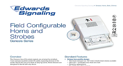
Edwards Signaling Catalog u Strobes Horns Bells Chimes Environment 8A Series Features UL 1971 listed synchronizing strobe strobes synchronize to the latest UL 1971 require when used with a synchronization source Genesis compatible Genesis and Integrity strobes on the same circuit meet UL synchronization requirements when used with an external module Approved for public and private mode applications 1971 listed as signaling devices for the hearing impaired UL 1638 listed as protective visual signaling appliances Rugged red or white steel front plate for outdoor or harsh environments Rated for wall or ceiling installation Field changeable field markings language or standard marking is easily changed optional LKW and LKC series lens kits Fits 4 inch square flush box for retrofit and renovation projects UL ULC rated outdoor option Series strobes are specially designed for use with compat life safety communication and control equipment to alert the impaired of a life safety event Strobes are available with cd and 110 cd effective flash intensity They are fully com with Genesis signals Series strobes exceed UL synchronization requirements 10 milliseconds other over a two hour period when with a separately installed EG1M Signal Master or E NAC Module or when powered by suitably enabled power supplies and control panels flash from CS405 Series strobes can be noticed from almost position in the room corridor or large open space CS405 strobes are UL 1971 listed with both wall and ceiling cd ratings see Specifications This is useful in areas where Authority Having Jurisdiction AHJ permits ceiling mount Series strobes are designed for 16 to 33 Vdc operation must be connected to signal circuits that output a constant pulsed voltage A diode is used to allow full signal circuit and polarized connections are made to terminals that up to 12 AWG 2.5mm wire strobe front plate is of steel construction finished with durable epoxy polyester powder coat paint 1 of 4 D A T A S H E E T S85001 0305 to be used for installation purposes Issue 8 The installation of visible signals are subject to national and local standards codes and ordinances your Authority Having Jurisdiction for device installation requirements application standards and minimum performance specifications strobes are UL 1971 listed for use indoors as wall mounted notification appliances for the hearing impaired Prevail codes require strobes to be used where ambient noise conditions specified levels where occupants use hearing protection in areas of public accommodation Consult with your Authority Jurisdiction for details part of the Enhanced Integrity line of products CS405 Se strobes exceed UL synchronization requirements within 10 other over a two hour period when used with a source Synchronization is important because a portion of the population have a condition which may cause to become disoriented from multiple random flashes of light strobes minimize this risk strobes are fully compatible with Edwards Genesis sig The flash intensity of some visible signals may not be adequate alert or waken occupants in the protected area Research indicates the intensity of strobe needed to awaken 90 of sleeping persons approximately 100 cd Edwards recommends that strobes in sleeping be rated at at least 110 cd These devices will not operate without electrical power As frequently cause power interruptions further safeguards such as power supplies may be required Current RMS Vdc Vfwr cd Vdc Vfwr cd Volts direct current regulated and filtered Volts full wave rectified and Mounting models fit to a standard flush mounted North American four electrical box 1 1 2 inch 38 mm deep minimum Optional weatherproof surface mount boxes are available The must be connected to signal circuits which output a not pulsed voltage Edwards recommends that these always be installed in accordance with the latest recog edition of national and local fire alarm codes mm cd cd Draw Notes and Comments Current values are shown in mA UL Nameplate Rating can vary from Typical Current due to measurement meth and instruments used Edwards recommends using the Typical Current for system design including NAC Power Supply loading and voltage drop calculations Use the 16 Vdc RMS current ratings for filtered power supply and battery AH Use the 16 Vfwr RMS current ratings for unfiltered power supply Fuses circuit breakers and other overcurrent protection devices are typically for current in RMS values Most of these devices operate based upon heating affect of the current flowing through the device The RMS current the heating affect and therefore the trip and hold threshold for those Wiring 24 Vdc Strobe an end of resistor on the device resistor with panel Listed dc Alarm Panel circuit 2 of 4 VIEW MOUNTED Lens Marking LKW or LKC Series mm Philip screws are provided secure unit onto electri box Plastic Caps are pro for indoor mounting mm mm D A T A S H E E T S85001 0305 to be used for installation purposes Issue 8 Distribution cd 7A Series Strobes cd 5A Series Strobes cd 7A Series Strobes cd 5A Series Strobes cd 3A Series Strobes cd 7A Series Strobes cd 3A Series Strobes cd 4A Series Strobes cd 3A Series Strobes cd 4A Series Strobes cd 8A Series Strobes cd 4A Series Strobes cd 8A Series Strobes cd 8A Series Strobes Output Output Output Output Output e grees e grees e grees Output Output Output e grees e grees e grees Output Output Output e grees e grees e grees Output Output e grees e grees Output e grees 20 10 20 30 20 30 100 100 100 Output Output Output Output Output Output Output Output Output Output Output Output Output