Edwards Data Sheet Genesis Outdoor Speakers and Speaker Strobes

File Preview
Click below to download for free
Click below to download for free
File Data
| Name | edwards-data-sheet-genesis-outdoor-speakers-and-speaker-strobes-0143685279.pdf |
|---|---|
| Type | |
| Size | 1.32 MB |
| Downloads |
Text Preview
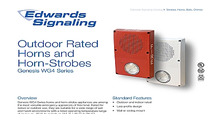
Edwards Signaling Catalog u Speakers Telephones pending Features Outdoor and indoor rated Low profile design Wall or ceiling mount Room side wiring accepts 18 to 12 AWG 0.75 to 2.5 mm2 Wide operating temperature range Field selectable speaker wattage voltage and strobe candela Field configurable temporal strobe output option Fully compatible with Genesis synchronization protocols Standard and high output strobe intensities Speaker only and Speaker Strobe appliance options Rated and WG4 Series WG4 Series speakers and speaker strobe appliances among the most versatile emergency appliances of their kind for indoor or outdoor use they are suitable for a wide range wet and harsh environments with a listed operating temperature of as low as 31 to as high as 151 35 to 66 light and sound output settings add to their on flexibility while optional FIRE markings make them ideal for fire applications appliances are suitable for indoor and outdoor applications are ideal for challenging conditions such as parking garages process areas They are listed for mounting on the ceiling or wall and thanks to an ingenious full backplane sealing gasket be installed to recessed in the pour block electrical boxes signals also mount to suitable surface boxes served by race Optional color matched trim skirts provide a clean finished All appliance wiring is accomplished room side for installation Series appliances feature highly intelligible and efficient my loudspeakers These are dual voltage 25.2V or 70.7V have field selectable output taps ranging from 80.8 dBA to dBA The multi candela strobes are available with clear lens and in two output categories standard and high output They precision timed to meet UL 1971 synchronization standards field configurable for one of four candela intensities Wattage candela settings are viewable even after installation through innovative sealed viewport display 1 of 4 D A T A S H E E T S85001 0626 to be used for installation purposes Issue 1 Application suggested sound pressure level for each signaling zone used alert or alarm signals is a minimum of 15 dB above the aver ambient sound level or 5 dB above the maximum sound level a duration of at least seconds whichever is This is measured 5 1.5 m above the floor in anechoic chamber Sound Output dBA two watts the distance from signal to the ear will cause a 6dB in the received pressure level The effect depends on acoustic properties of in the space Dou the power output of a e g a speaker from to 2W will increase the pressure level by 1.5m 3.05m Series Cone Speaker strobe Application clear lensed strobes are UL 1971 listed for use indoors wall or ceiling mounted public mode notification appliances for hearing impaired and UL 1638 listed for outdoor applications codes require strobes to be used where ambient noise exceed specified levels where occupants use hearing and in areas of public accommodation appliance synchronization is required to avoid causing with people who have Photosensitive Epilepsy PSE Noti appliance synchronization is also generally required when than one strobe appliance are in the same field of view from one location All Genesis strobes meet UL synchronization within 10 milliseconds over a two hour period when with a synchronization source These devices will not operate without electrical power fires frequently cause power interruptions we suggest you discuss safeguards with your local fire protection specialist recommends that these devices always be installed in with the latest recognized edition of national and local Refer to the appropriate codes and standards for mounting information and Mounting b t le tric s t e tio e r t c r o x e r r e signals are rated for use and are for indoor or applications on or ceilings For in or wet applica appliances must be to an Edwards electrical box In dry they are with standard by 1 deep boxes When the optional or WG4RTS trim skirt a 449 or 2 1 8 deep box must used Genesis WG4 Speaker Strobe may be wall or ceiling mount and may be placed in one of four positions strobe above below and strobe to either side The shallow depth of devices leaves room behind the appliance for extra wiring Configuration WG4 speakers may be set to 70 or 25 Volt operation for 1 or 2 watt operation The wattage setting repre by the letters Z Y X and T is changed by removing the and simply sliding the S1 switch until the desired setting ap The setting remains visible through a small window on the of the device after the cover is installed The voltage setting or 25V is toggled at S3 This setting is not visible after the is replaced WG4 speaker strobes also feature selectable candela The actual light output for a given selection depends on it is a high output model or a standard output model Re to the specification tables for corresponding settings The can setting represented by the letters D C B and A is changed removing the cover and simply sliding the S2 switch until the setting appears The setting remains visible through a window on the front of the device after the cover is installed Speaker Strobe temporal selection speaker strobes may also be configured for temporal This power saving feature is intended for private mode only To set the device for temporal flash snip the jumper JP1 2 of 4 D A T A S H E E T S85001 0626 to be used for installation purposes Issue 1 voltage voltage response size strobe boxes environment humidity VRMS or 70 VRMS switch selectable VRMS VDC 24 VFWR nominal V max to 4,000 Hz to 18 AWG 0.75 to 2.50 mm EG1M RM EBPS6A EBPS10A 3 5 and 10 zone E FSA64 E FSA250 Model 449 WG4 trim skirt recommended 4 square by 1 1 2 deep box when used a trim skirt When trim skirt is used must be 4 square by 2 1 8 deep to 151 35 to 66 to 95 noncondensing Position level output dBA W W W W V V Decibels A weighted 1480 Sound level output at 10 ft 3.05 m measured in a reverberant using 400 to 4,000 Hz band limited pink noise wiring is connected to Genesis signals with terminals that ac 18 to 12 AWG 0.75 mm to 2.5 mm wiring off axis candela requirements as a percent of the UL rated output output Angle rating UL 1971 candela rating UL 1638 candela 15 10 15 20 Switch Position