Edwards E-IDC1B Analog Single Input Mini Module Installation Sheet

File Preview
Click below to download for free
Click below to download for free
File Data
| Name | edwards-e-idc1b-analog-single-input-mini-module-installation-sheet-1943865702.pdf |
|---|---|
| Type | |
| Size | 726.53 KB |
| Downloads |
Text Preview
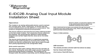
Analog Single Input Mini Module Sheet E IDC1B Analog Single Input Mini Module is an analog device used to connect a normally open alarm or monitor type dry contact initiating device IDC to a control panel This module is designed for B circuit operation device address is set using the two rotary switches on the front of the module One device address is module is factory set to operate as an alarm latching When the NO contact of an initiating device is an alarm signal is sent to the control panel and the condition is latched at the module device types are available through front panel or the configuration utility For additional refer to the documents listed on the control label provides two status LEDs The LEDs are visible from back of the module 1 LED location module does not operate without electrical power fires frequently cause power interruption discuss safeguards with the local fire protection module does not support conventional two wire detectors The module is shipped from the factory as an unit it contains no user serviceable parts and not be disassembled install the module Verify that all field wiring is free of opens shorts and faults Make all wiring connections as discussed in shown in Figure 3 Set the required device address For example to set the address for 21 set the TENS switch marked 0 12 to 2 and the ONES switch marked 0 to 9 to 1 Figure 2 devices can be addressed from 01 to 129 Panel may vary Position the module into the electrical box behind the to which it connects 2 Module address 6 5 9 screwdriver here Red LED Alarm active Green LED Normal 2013 UTC Fire Security All rights reserved 2 3101190 REV 03 REB 25JAN13 in accordance with NFPA 72 and CAN ULC S524 for the Installation of Fire Alarm Systems and in with the local authorities having jurisdiction sure to observe the polarity of the wires as shown in 3 wiring is power limited and supervised module does not support two wire smoke detectors 3 Module wiring 6 5 9 Refer to the control panel technical reference manual for wiring Wire nut or other listed splice connector or terminal block Style B Class B Typical NO initiating device maximum line fault impedance device circuit IDC resistor value resistance capacitance environment humidity temperature range VDC at 350 V peak to peak k k P N EOL 47 25 per wire max max to 120 0 to 49 to 93 noncondensing to 140 to 60 information A Division of UTC Fire Security Corporation Inc Town Center Parkway Bradenton FL USA first two digits of the product serial number on the product identification label are year of manufacture Indoor dry 864 CAN ULC S526 information contact information see our Web site of American of 2 3101190 REV 03 ISS 25JAN13