Edwards E-PD Photoelectric Smoke Detector Installation Sheet

File Preview
Click below to download for free
Click below to download for free
File Data
| Name | edwards-e-pd-photoelectric-smoke-detector-installation-sheet-7541823096.pdf |
|---|---|
| Type | |
| Size | 660.05 KB |
| Downloads |
Text Preview
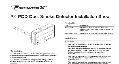
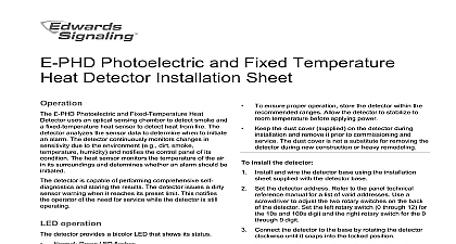
Photoelectric Smoke Detector Sheet E PD Photoelectric Smoke Detector uses an optical chamber to detect smoke The detector analyzes the data to determine whether to initiate an alarm The is capable of performing comprehensive self and storing the results The detector continuously changes in sensitivity due to the environment e g smoke temperature humidity and notifies the loop of its condition The detector issues a dirty sensor when it reaches its preset limit This notifies the of the need for service while the detector is still install the detector and wire the detector base using the installation supplied with the detector base Set the detector address Refer to the panel technical manual for a list of valid addresses Use a to adjust the two rotary switches on the back the detector See Figure 1 Set the left rotary switch 0 through 12 for the 10s and digit and the right rotary switch for the 0 through 9 Connect the detector to the base by rotating the detector until it snaps into the locked position head can be removed by turning it counterclockwise the head must lock to the base break away the locking using a pair of pliers See Figure 2 then remove the detector head after breaking away the tab insert a small screwdriver into the slot on the of the base and press in while simultaneously turning detector head counterclockwise 1 Setting detector address address 32 shown screwdriver here 2 Breakaway tab 6 4 5 9 Breakaway tab operation detector provides a bicolor LED that shows its status Green LED flashes Red LED flashes to Edwards Signaling Smoke and Heat Detectors Bulletin P N 3101212 for additional information detector placement and spacing detector does not operate without electrical power As frequently cause power interruption discuss further with the local fire protection specialist detector does not sense fires in areas where smoke reach the detector Smoke from fires in walls or on the opposite side of closed doors may not the detector detectors have a wide range of sensing but are best suited for detecting slow fires ensure proper operation schedule maintenance or selected in accordance with the requirements the authority having jurisdiction Refer to NFPA 72 and ensure proper operation store the detector within the ranges Allow the detector to stabilize to temperature before applying power the dust cover supplied on the detector during and remove it prior to commissioning and The dust cover is not a substitute for removing the during new construction or heavy remodeling 2013 UTC Fire Security All rights reserved 2 3101207 REV 03 REB 28JAN13 the detector cleaning is necessary the sensing chamber of the unsnaps for easy field cleaning and service clean the detector Remove the detector from the base a screwdriver in the small slot where the detector connects to the detector body See Figure 3 Pry the detector cap off the detector body Squeeze the optical block chamber where the two arrows labeled here Pull off the optical block chamber Blow off the optical block base in the detector body using compressed air Snap a new optical block chamber in place Make sure line up the two arrows on the block chamber with the on the optical block base Connect the detector cap to the detector body by rotating cap clockwise until it snaps into a locked position the detector onto the base To verify the effectiveness of the cleaning the device and run a device maintenance Refer to the technical reference manual Test the detector and verify sensitivity 3 Detector disassembly test the detector Before initial testing remove the dust cover from the and notify the proper authorities that the fire system is undergoing maintenance and will be out of service Test the detector using Smoke In A Can model SM 200 smoke Carefully follow directions on the can to damage to the detector line voltage operating current current sensitivity range compensation bases distance from ceiling temperature environment 20 V peak to peak to 3.66 ft obscuration to 3.70 ft obscuration B4U B4U LP RB4U IB4U SB4U in 305 mm to 140 to 60 to 120 0 to 49 to 93 RH noncondensing at 32 and compliance A Division of UTC Fire Security Corporation Inc Town Center Parkway Bradenton FL 34202 first two digits of the date code located on the identification label are the year of UL 268 ULC S529 02 NFPA 72 and CAN ULC S524 of American Slot to insert screwdriver Optical block chamber Detector body Optical block base Detector cap information contact information see our Web site edwardssignaling com 72 and CAN ULC S537 require a calibrated sensitivity upon completion of the original installation and following modifications or additions to the system The detector can this test and generate a system sensitivity report 2 3101207 REV 03 REB 28JAN13