Edwards EC-50R EC-100R User Guide

File Preview
Click below to download for free
Click below to download for free
File Data
| Name | edwards-ec-50r-ec-100r-user-guide-1594726803.pdf |
|---|---|
| Type | |
| Size | 703.83 KB |
| Downloads |
Text Preview
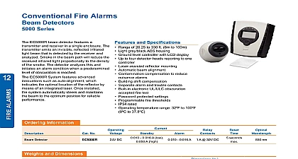
Guide Beam Smoke Detector Installation NFPA72 NOTE The infrared beam path MUST be kept clear of obstructions at times Failure to comply may result in the system initiating a Fire or Fault signal Detector installation must comply with local regulations UL listed products must comply Ensure clear line of sight between Detector and Reflector it is recommended at least radius of clear space be maintained around the centre of the beam path Mount securely to solid structural surfaces Position beam as high as possible but with a minimum distance of 0.5m from Detector to For installations complying with UL268 NFPA72 the maximum distance of and Reflector from the ceiling must be 10 of the distance between floor and Mount Detector and Reflector directly opposite each other Do NOT position Detector where personnel or objects can enter beam path Do NOT position two Detectors facing each other Do NOT install the Detector or Reflector in environments where condensation or icing are to occur For ranges between 5m and 50m use a 50m Detector with 1 Reflector For ranges between 50m and 100m use a 100m Detector with 4 Reflectors User Configuration Settings to the configuration settings is through the back plate of the Detector Head Factory configuration settings are marked switch Reset Fire Relay 5 seconds Fire Relay Relay Enable On Compensation Limit Relay Disable On Compensation Limit Threshold Threshold Threshold Threshold Use for extreme sensitivity The Detector is set to Latching Mode or Auto Reset Mode using DIP Switch 1 If in Auto OFF Mode the Detector will automatically recover from a Fire state when the fire has been removed If in Latching Mode it will remain in Fire state until either the is placed in Prism Targeting Mode or Alignment Mode then back to Operating OR power is removed from the Detector for 10 seconds Fire Relay Enable Disable on Compensation Limit is set with DIP Switch 2 This mode whether Fire activation is still enabled during an AGC Compensation Fault The Sensitivity of the Detector is set using DIP Switches 3 and 4 Do not use the 12 or 25 Alarm threshold for UL listed 100m Detectors as this will not to UL268 Wiring Diagram BLACK BLUE WHITE note 1 YELLOW Relay Relay to 30 Volts DC RED WIRING connection of a single conventional Detector to a zone 1 This component is the Fire Resistor and its value is specified by the Fire Control Manufacturer For US installations it is typically a short circuit End of Line component supplied by the Fire Control Panel manufacturer Analogue Addressable variants Panel GREEN Output switches to Unit Line BLACK BLUE GREEN WHITE note 1 note 2 YELLOW Relay Relay to 30 Volts DC RED WIRING connection of multiple conventional Detectors to a zone 1 This component is the Fire Resistor and its value is specified by the Fire Control Manufacturer For US installations it is typically a short circuit Schottky Diode 60Volt 1 Amp typical must be UL listed for installations meeting End of Line component supplied by the Fire Control Panel manufacturer to 30 Volts DC RED Relay Relay YELLOW note 1 WHITE GREEN BLUE BLACK Prism Targeting Mode power to the Detector After 5 seconds the RED LED will flash once to indicate that the is a 50m detector or twice to indicate a 100m detector Detector operating mode is selected the Mode Switch situated on the rear the unit It can be accessed by sliding a between the body of the unit and the NOT remove the detector from the when accessing the Mode Switch Prism Targeting Mode by moving the Mode Switch to the upper position the prism by adjusting the horizontal and vertical thumbwheels until the AMBER LED is ON The AMBER LED will be OFF when no signal is being received then will at an incrementing rate to determine the target position The faster the flash the nearer are to the target prism this point it is essential to test that the prism and not another surface is reflecting beam Cover the prism with a non reflective material and confirm that the AMBER LED OFF Alignment Mode Alignment Mode by moving Mode Switch to the middle position The Detector will adjust its infrared beam power and receiver sensitivity to give an optimum signal strength The progress of this is indicated by the LEDs on the front of the CONTINUOUSLY AMBER The Detector is not receiving a signal Go back to prism mode FLASHING RED The Detector is receiving too much signal and is attempting to reduce infrared power output to compensate Wait at this point until the LED is OFF this may up to 20 seconds depending on the distance between Detector and Prism the the distance the longer the time FLASHING AMBER The Detector is receiving a weak signal and is attempting to the infrared power output OFF The Detector has optimised the infrared power and receiver gain for the current of the Detector and Prism This does not mean that the Detector to Prism is at its optimum i e if the power is too high a misaligned Detector may be a fringe reflection from another object FLICKERING RED AMBER This state can occur sometimes It means that the infrared is stepping through the optimum setting to flow for procedure to Prism Mode Process Flow Diagram the of the for the the alignment mode AMBER will illuminate for seconds until both LED stop up to 30 seconds adjust a thumbwheel in direction and observe the LED turning the and wait the Red LED to flashing turn the in the direction turning the optimum alignment of the beam in all planes should cause Amber LED to flash first Alignment and enter Mode Operating Mode Operating Mode by moving the Mode Switch to its lower position exiting alignment mode the Detector will perform an internal calibration check Do not the beam whilst this internal calibration takes place The Amber LED will flash a second for up to sixty seconds and then go out If this fails which would be due to alignment or either electrical optical noise the detector will indicate a Fault condition In case the alignment procedure must be repeated the internal calibration check completes satisfactory the Detector will now be in normal mode System Testing successful installation and alignment the System will require testing for both alarm and conditions Trouble Test a non reflective object quickly cover the entire prism s The Detector will indicate a within 10 seconds by activating the FAULT LED and operating the Fault Relay fault condition will automatically reset when the obstruction is removed Smoke Test note of th