Edwards F-Series Remote Annunciator Installation Sheet

File Preview
Click below to download for free
Click below to download for free
File Data
| Name | edwards-f-series-remote-annunciator-installation-sheet-2504813796.pdf |
|---|---|
| Type | |
| Size | 844.35 KB |
| Downloads |
Text Preview
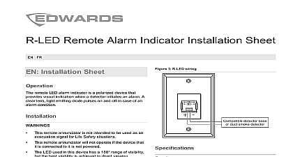
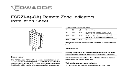
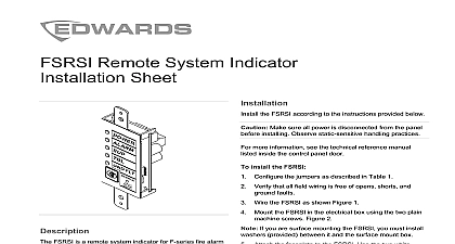
F Series Remote Annunciator Installation Sheet FR Alarm Fault Test Alarm Fault Silence Drill Test 2011 UTC Fire Security All rights reserved 4 3101146 ML REV 3.0 ISS 08AUG11 1 FSRA10 2 FSRA10C 3 Mounting diagram Compatible electrical box Mounting plate 8 1 4 screw 4 Annunciator rear view 5 Wiring diagram From control panel or auxiliary or booster power From control panel To next remote module On Group 1 Off Group 2 Remote annunciator key switch RKEY wiring is supervised and power limited twisted pair cables for data wiring power supplied by the control panel can exceed 0.5 A If than 0.5 A is required you must use a power limited and 24 VDC auxiliary booster power supply that is UL ULC for fire protective signaling systems powered from an external supply the supply must be installed the same room as the control panel and their 24 VDC wired together RKEY switch wiring is not supervised The switch must be within 3 feet 91 m of the annunciator in the same room enclosed in conduit or is equivalently protected against injury Attach the mounting plate to the electrical box See Configure the remote annunciator for peripheral group 1 or Wire the remote annunciator See Figure 5 Attach the RKEY switch wiring to the annunciator See Set the remote annunciator on the mounting plate and secure it with the set screw 3 2 5 Installation Sheet remote annunciators provide remote LED indicators controls for 10 zone F series control panels The FSRA10 system status LEDs ten zone active LEDs and ten trouble LEDs The FSRA10C provides system status ten zone active and zone trouble LEDs and common installation sheet applies to the remote annunciator listed in Table 1 1 Compatible models remote annunciator with system status LEDs overlay remote annunciator with system status LEDs overlay remote annunciator with system status LEDs common controls English overlay remote annunciator with system status LEDs common controls French overlay remote annunciators are configured using the jumpers in Table 2 2 Group selection jumper peripheral group 1 peripheral group 2 Limit one annunciator per peripheral group 4 3101146 ML REV 3.0 ISS 08AUG11 current current fault impedance 0 size electrical H D environment to 27.3 VDC and continuous mA mA to 12 AWG 0.75 to 2.50 mm to 12 AWG 0.75 to 2.50 mm twisted 6 twists per foot minimum American 4 inch square electrical box listed enclosure 8 1 2 1 1 2 in 14.3 21.4 cm to 120 0 to 49 to 93 noncondensing information A Division of UTC Fire Security Corporation Inc Town Center Parkway Bradenton FL USA first two digits of the DATE MFG number on the product identification label are year of manufacture device complies with part 15 of the FCC Operation is subject to the following two 1 This device may not cause harmful and 2 this device must accept any received including interference that cause undesired operation Indoor dry 3K5 of compliance information contact information see www utcfireandsecurity com Feuillet d avertisseurs distance de s F se composent de distance et de commandes pour le panneau de de s F 10 zones Le FSRA10 se compose de d du syst de voyants d dix zones et voyants de panneau dix zones Le FSRA10C se compose voyants d du syst de voyants d dix zones de voyants de panneau dix zones ainsi que de communes fiche d s aux mod d d dans le Tableau 1 1 Mod compatibles distance 10 zones avec voyants d syst anglais distance 10 zones avec voyants d syst fran distance 10 zones avec voyants d syst et commandes communes anglais distance 10 zones avec voyants d syst et commandes communes fran avertisseurs distance du FSRA10 C sont configur utiliser les cavaliers d dans le Tableau 2 2 Cavalier s de groupe S le groupe p 1 le groupe p 2 Un seul avertisseur distance par groupe p 1 FSRA10 2 FSRA10C 3 Sch de montage Bo compatible Platine de support Vis 8 1 4 4 L distance vue arri 5 Sch de c Du panneau de commande ou d auxiliaire ou d amplificateur de Du panneau de commande Au prochain module distance Marche Groupe 1 Arr Groupe 2 Commutateur d avertisseur distance RKEY le c est contr par un courant permanent avec limit un c torsad pour le c des donn AUX transmise par le panneau de commande ne d 0,5 A Pour une intensit sup 0,5 A vous utiliser une alimentation de survolteur auxiliaire de 24 V r et puissance limit qui est list sous UL ULC les syst de d de protection incendie l est aliment par une source externe l provenir de la m pi que le panneau de commande et c communs 24 V c c c du commutateur RKEY n est pas supervis Le doit situ moins de 3 pieds 91 m de distance dans la m pi et inclus dans le ou est d une mani equivalente prot contre des m plus de renseignements reportez vous au manuel de technique se trouvant dans la porte du panneau de 3101146 ML REV 3.0 ISS 08AUG11 4 Fixez la plaque de montage la bo Figure 3 Configurez l distance pour le groupe 1 ou 2 Branchez l distance Voir Figure 5 Attachez le c du commutateur de RKEY distance Voir la Figure 5 l distance sur la plaque de montage fixez le avec les vis techniques de d la de c