Edwards FSRSI Remote System Indicator Installation Sheet

File Preview
Click below to download for free
Click below to download for free
File Data
| Name | edwards-fsrsi-remote-system-indicator-installation-sheet-8694502317.pdf |
|---|---|
| Type | |
| Size | 737.23 KB |
| Downloads |
Text Preview
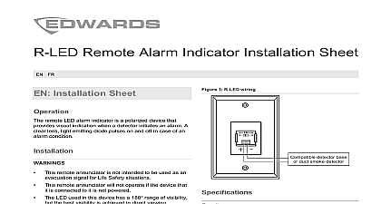
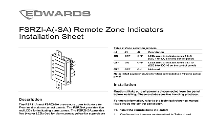
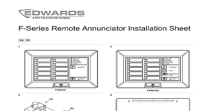
Remote System Indicator Sheet the FSRSI according to the instructions provided below Make sure all power is disconnected from the panel installing Observe static sensitive handling practices more information see the technical reference manual inside the control panel door install the FSRSI Configure the jumpers as described in Table 1 Verify that all field wiring is free of opens shorts and faults Wire the FSRSI as shown Figure 1 Mount the FSRSI in the electrical box using the two plain screws Figure 2 If you are surface mounting the FSRSI you must install provided between it and the surface mount box Attach the faceplate to the FSRSI Use the two white screws provided with the faceplate FSRSI remote system indicators will not operate until detected by the control panel For more see the technical reference manual listed inside control panel door 1 FSRSI wiring diagram panel 24 VDC control panel or power supply 3 remote Group 1 Group 2 FSRSI is a remote system indicator for F series fire alarm panels The FSRSI provides five LEDs and a buzzer to AC power status alarm events supervisory events events and ground fault events The FSRSI also a local silence button to turn the buzzer off without the LED indicators remote system indicators include a cover plate for in a standard single gang electrical box You can install the FSRSI with one or two remote zone indicators an approved 2 3 or 4 gang electrical box Cover plates for 3 or 4 gang electrical boxes model numbers FSAT2 or FSAT4 are ordered separately remote system indicators are configured using the described in the table below 1 Group selection jumper Only one FSRSI is allowed per peripheral group peripheral group 1 peripheral group 2 2013 UTC Fire Security All rights reserved 2 3101034 REV 02 REB 25JAN13 All wiring is supervised and power limited AUX power supplied by the control panel can exceed 0.5 If more than 0.5 A is required you must use a power and regulated 24 VDC auxiliary booster power that is UL ULC Listed for fire protective signaling powered from an external supply the supply must be in the same room as the control panel and their VDC commons wired together 2 Installing the FSRSI in a single gang electrical box 1 gang electrical box capacitance resistance fault impedance size electrical box indicators operation Humidity environment to 27.3 VDC mA at 24 VDC mA at 24 VDC max ohms max to 18 AWG 0.75 to 2.5 sq mm OS1 1996 1 to 4 gang box power green alarm red yellow trouble yellow fault yellow trouble event temporal alarm slow pulse supervisory event AC fail event to 120 0 to 49 to 93 RH noncondensing 2 3101034 REV 02 REB 25JAN13